Starting Up HMI Embedded (IM2) 08/2005
4 Functions/Parameterization
© Siemens AG, 2005. All rights reserved
IM2/4-68 SINUMERIK 840D sl/840D/840Di/810D HMI Installation and Start-Up Guide (IAM) – 08/2005 Edition
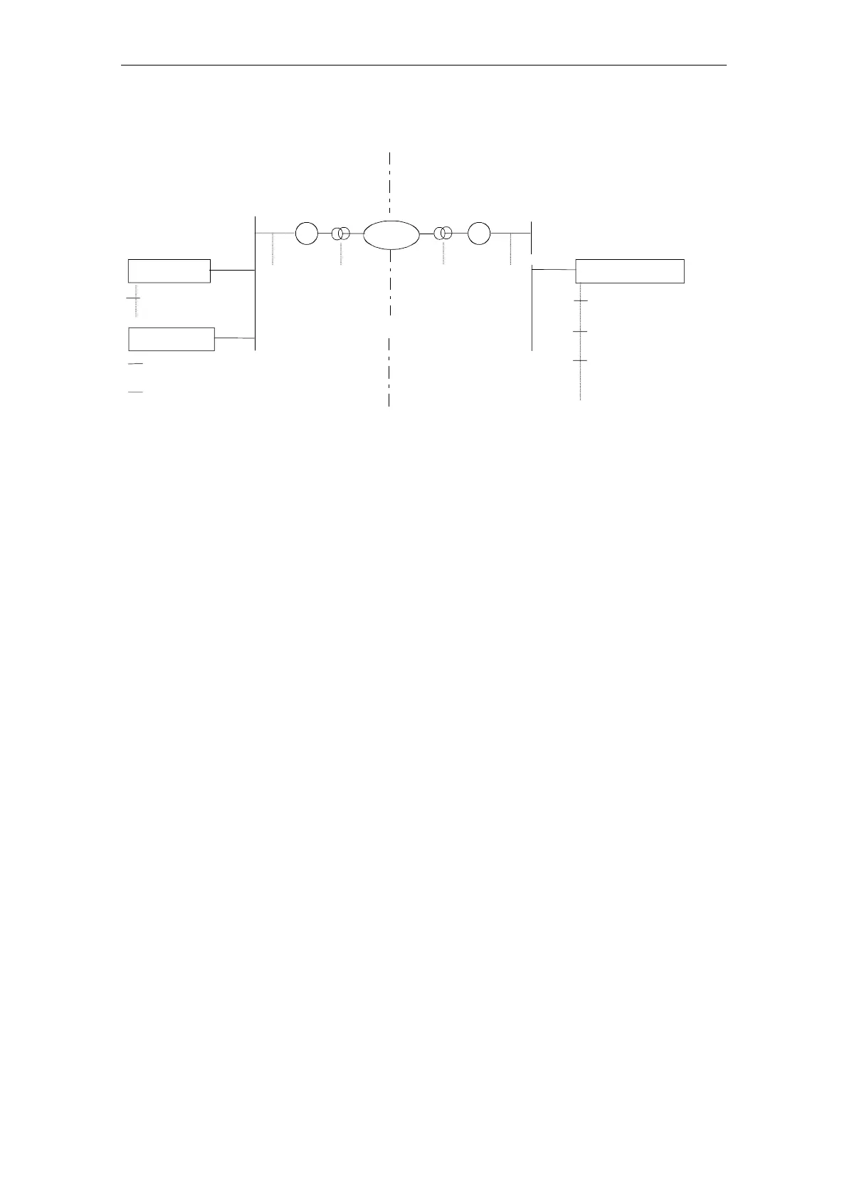
Structure example of an ISDN connection:
WAN
ISDN Netw.
HW Router
Cisco 803
BRIO Interface
192.168.254.1
Ethernet
174.1.1.1
LAN
(Ethernet) private
Host:
IP 192.168.254.4
Host: Remote PC
IP 192.168.254.129
Process: UDP Ping (Server)
on Port 9999
Process: "RCS Viewer NCU 7x0" (Client)
Target: 192.168.12.238:5800
Process: File transfer (Server)
"Netzwork Manager" application
Share folder Port 19000
BRIO Interface
192.168.12.237
HW Router
Cisco 803
Remote PC (Viewer)
NCU 7x0 (Host)
Ethernet
172.1.1.1
NCU 7x0 (HMI Embedded)
Host: IP 192.168.12.238
172.1.1.2
LAN
(Ethernet) private
Process: UDP Ping (Client)
Target: 192.168.254.4:9999
Process: "RCS Host NCU 7x0"
(Server) on Port 5800
Process: File transfer (Client)
Tunnel Connection
(VPN)
Fig. 4-6 Example: Connection structure of the remote diagnosis
Remote diagnosis sequence
A machine manufacturer who provides this service has selected an appropriate
topology for a tunnel connection and will provide support when setting up the
remote diagnosis.
The relevant "Ping server" on the remote PC must be activated for this purpose.
This server has the task of accepting the incoming "Ping" data (e.g. serial number)
of the requesting machine and registering the IP address of the requesting
machine. If this server application is not provided by the service provider, it is
possible to configure the RCS viewer application so that a simple “Ping” server
process can be started on the RCS Viewer. The IP address, the port and the
protocol used for this Ping server are specified by the service provider and must be
set on the machine.
The remote diagnosis is initiated by the machine. The NCU 7x0 is connected to the
appropriately configured router via an Ethernet cable and starts the remote
diagnosis process via the operating interface. The NCU 7x0 then sends cyclically
preset "Ping" data to the remote PC and waits for its response. The transmission of
the "Ping" causes the router to establish the connection (e.g. switched ISDN
connection).
When the response is received from the remote PC, the NCU 7x0 is ready for the
data communication for the remote diagnosis. For this, a server process is started
on the NCU 7x0 which is responsible for the exchange of graphic information to the
remote PC and the keyboard inputs from the remote PC.
The exchange is performed via the TCP/IP protocol and a "permanently" agreed
port. A so-called "Viewer" application (mmcR.exe) is installed on a remote PC as
communication partner. From now on, all further activities will be initiated by the
remote PC.

 Loading...


