08/2005 Commissioning HMI Advanced (IM4)
2 Setting Functions and Parameters
© Siemens AG, 2005. All rights reserved
SINUMERIK 840D sl/840D/840Di/810D Installation and Start-Up HMI (IAM) - 08/2005 Edition
IM4/2-33
The HMI itself does not have to react to this change. The PLC can only write data
to the interface again if the variable is set to “0”. This mechanism ensures that the
HMI knows about all parameter changes.
Configuring OEM icons
OEM icons indicating the machine state can be output in the field provided for the
program control display (e.g., SBL, MO1, etc.). If OEM icons are defined, the
elements for the program control display are hidden.
The icon names are identified in the HEADER.INI configuration file, same as the
user icons.
[OEMICONS]
OI_0= <name.bmp>, <Position>
...
OI_31= <name.bmp>, <Position>
Here, <name> is the file name of the bit map and <Position> is the output position
(from 1 to 16) in the display line. Multiple bit maps can be output at the same
position. If more than one bit map is active simultaneously at the same position, the
bit map with the highest screen number is displayed.
The output is controlled by means of a PLC double word. This double word is
declared in the next section in the HEADER.INI file.
[OemIcons]
Oem_ICON_BASE = DBx.DBBy
Each bit in this double word represents exactly one OEM icon corresponding to the
screen number. Thus, if Bit 0 is set, bit map OI_0 is displayed. If a bit is reset, the
associated bit map is deleted.
A maximum of 16 icons can be displayed, enabling a total of 16 display positions.
Empty positions need not be specified.
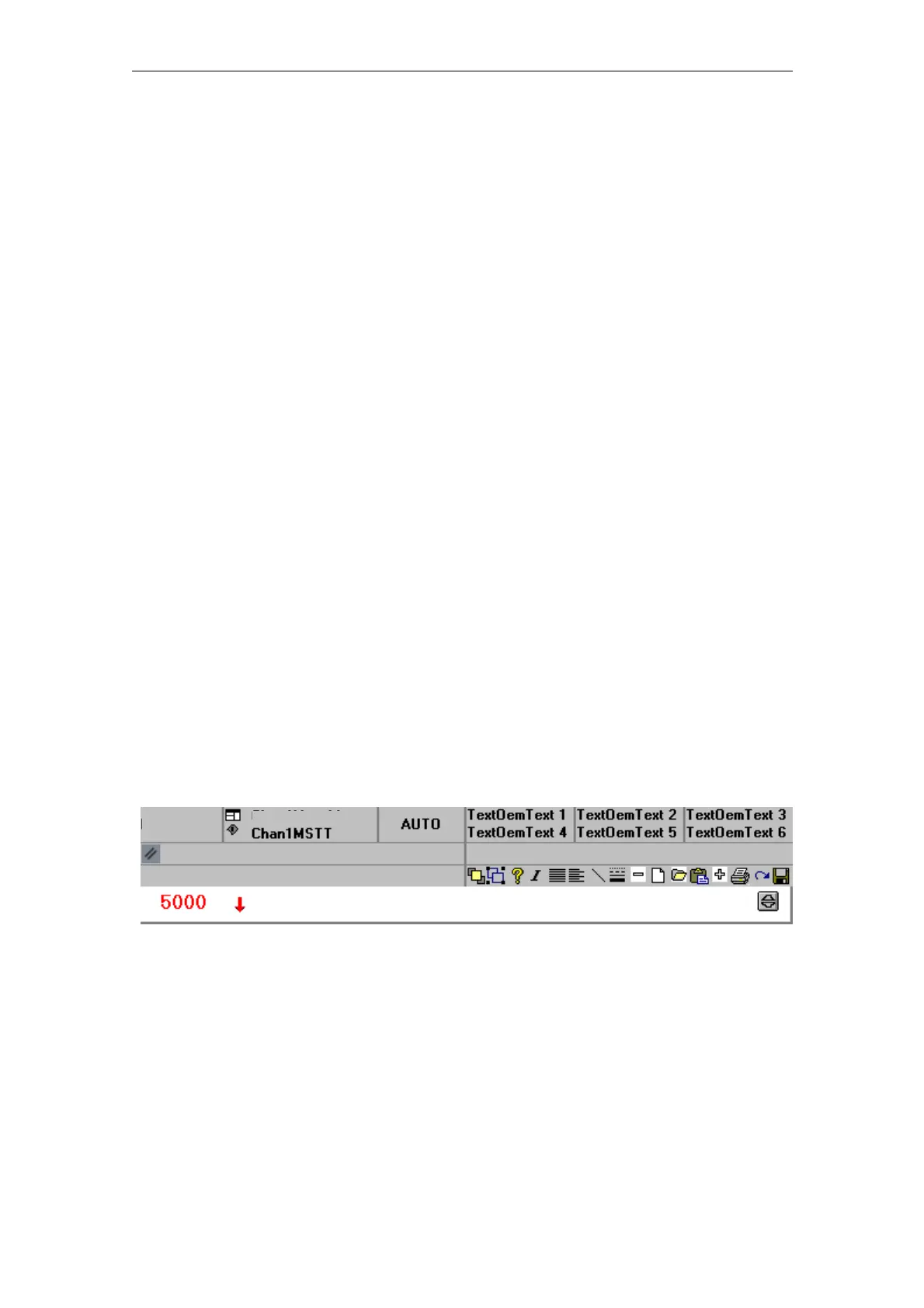
Chan 1 Machine
Machine
Channel RESET
Program Aborted
Communication job cannot be executed
Figure 2-5 Example of OEM icons

 Loading...


