Section 04 TRANSMISSION
Sub-Section 05 (PULLEY DISTANCE AND ALIGNMENT)
04-05-4
Move the engine to obtain specified pulley align-
ment, torque engine support bolts to 55 N•m (41
lbf•ft) and remove engine support positioner.
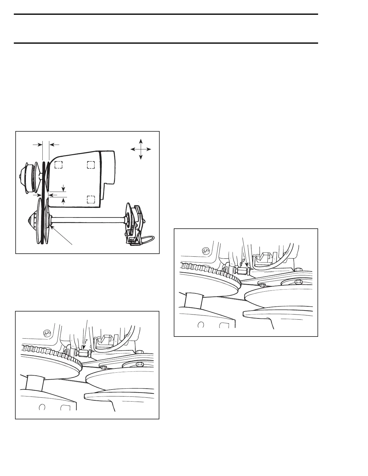
Driven Pulley Movement
Shims can be mounted between chaincase and
frame. Use shim (P / N 504 0398 00), 0.53 mm
(.021 in) thick.
S-Series
TYPICAL
1. Engine movement
2. Contact
NOTE :
Prior to performing pulley adjust-
ment, loosen torque rod nut to allow engine
movement. Engine supports have tendency to
stick to frame, work engine loose prior to aligning.
1. Loosen
Pulley Distance Adjustment Method
Engine Movement
The engine support has slotted mounting holes.
Move engine to obtain specified distance be-
tween pulleys.
Pulley Alignment Method
Driven Pulley Movement
When engine slotted mounting holes do not allow
to set proper pulley offset X, adjust with shims
(P / N 504 1082 00) between pulley and counter-
shaft bearing support (pulley pushed toward
brake disc).
Engine Movement
Loosen the 4 bolts retaining engine support to the
frame. Position engine to obtain the specified
alignment.
NOTE :
After alignment, adjust torque rod
so it slightly contacts stopper plate. Do not
over tighten, it will disalign pulleys.
1. Retighten
1
A15D02A
Y
X
Z
2
A06D07B
1
'
A06D07A
1