Section 03 ENGINE
Sub-Section 02 (599, 699 AND 809 ENGINE TYPES)
03-02-11
ASSEMBLY
2,3, Crankshaft Bearing, Anti-seize
Lubricant and Labyrinth Sleeve
Smear anti-seize lubricant (P/N 413 7010 00) on
part of crankshaft where bearing fits.
Prior to installation, place bearings into an oil con-
tainer filled with oil previously heated to 75°C
(167°F). This will expand bearing and ease instal-
lation.
809 Engine Only
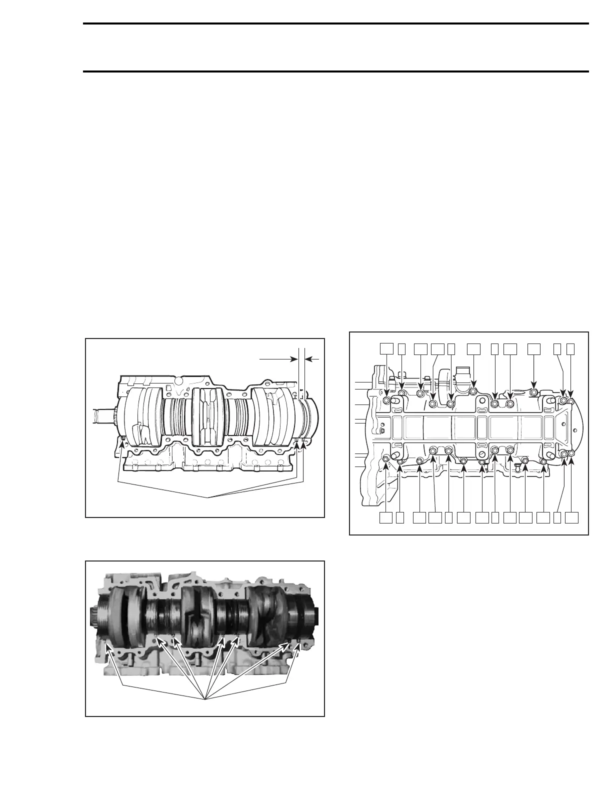
Last PTO bearing is 8 mm (5/16 in) from inner
bearing.
4, Crankcase
At crankshaft installation, position drive pins as il-
lustrated.
809 ENGINE
1. Drive pins
A. 8 mm (5/16 in)
599 AND 699 ENGINES
1. Drive pins
Crankcase halves
no. 4
and water pump housing
are factory matched and therefore, are not inter-
changeable as single halves.
Prior to joining of crankcase halves, spray some
new injection oil (or equivalent) on all moving
parts of the crankshaft. Spray Primer N (P/N 413
7081 00) on one of mating surfaces. Let it dry for
10 to 20 minutes.
Apply paste gasket (P/N 413 7027 00) on the other
mating surface.
NOTE:
Primer N allows Loctite 515 to fully cure
on aluminum surfaces. It increases filling capacity
and reduce curing time.
Torque crankcase screws in the following illustrat-
ed sequence. Tightening torques are:
M6 screws: 12 N•m (106 Ibf•
in
)
M8 screws: 30 N•m (22 Ibf•ft)
TYPICAL
5, Water Pump Housing
Apply silicone 732 RTV on sealing surface.
Tighten water pump housing screws to 10 N•m
(90 lbf•
in
) following sequence as illustrated.
A06C0HA
1
A
A06C22A
1
A06C3QA
23
6 20
17
1
15
4
13 11
8 9
7
10121416
2
1819
3
2122
5
24