06-1
Section 06 AIR SUSPENSION SYSTEM
AIR SUSPENSION SYSTEM 0
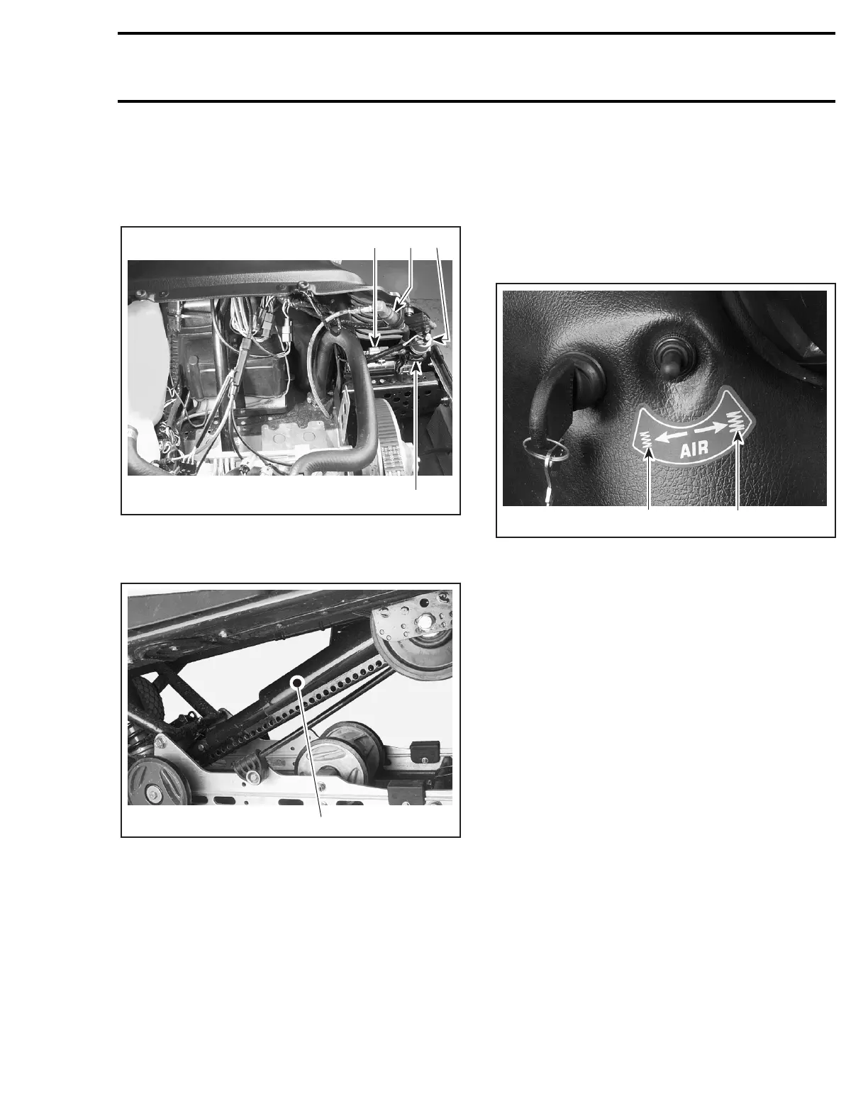
COMPONENT LOCATION
1. Compressor
2. Release valve
3. Desiccator
4. Pressure sensor
1. Pneumatic shock absorber
THEORY AND OPERATION
A compressor creates a pressure within the rear
shock absorber.
This shock absorber has been designed from a
conventional shock absorber to which an airtight
chamber has been added. A rubber boot connects
the shock absorber body to the shock absorber
piston rod.
The pressure in the air chamber increases when
the compressor is activated, and it decreases
when the release valve is activated. The compres-
sor and the release valve are controlled by a three-
way switch.
1. Activates the release valve
2. Activates the compressor
This shock absorber prevents the suspension
from bouncing just like a conventional shock ab-
sorber. The air pressure within acts as a spring by
increasing the preload.
TESTING PROCEDURE
Air Suspension System Tightness
Activate the compressor until the dashboard pres-
sure gauge indicates more than half.
Remove the ignition key.
Connect an ohmmeter to pressure sensor con-
nectors. No polarity need to be observed.
NOTE:
The pressure sensor electrical resistance
varies according to system pressure.
Note resistance and wait 3 minutes. The resis-
tance should not decrease. If it does, there is a
leak in the air system.
A06H30A
1
4
3
2
A06F2JA
1
A06H2VB
2
1