1-8
PDW-700/V1 (E)
of the AT-177 board. The viewfinder uses the time data for
displaying the time. The data for year, month, day, and
time of the clock can be changed using the menu.
The settings for year, month, day, and time are sent to the
FP_CPU and the year, month, day, and time are written to
the Real Time Clock IC.
6. WARNING_LED control and alarm tone control
The WARNING information is supplied from the ITRON
(CPU) that is used to turn on and off the WARNING LED
on the FP-157 board.
The 1 KHz square wave generated from the PWM genera-
tor circuit inside the FP_CPU alarm tone is used as the
alarm tone.
7. Wireless Receiver Control (Optional function)
This communication circuit can control both analog and
digital wireless receivers.
Analog wireless receivers use the conventional method of
synchronous serial communication (200 Bps).
(Interval time: 80 ms)
Digital wireless receivers use 38 KBps asynchronous serial
communication to handle large amounts of communication
data.
With a built-in wireless receiver, when FP_CPU is in the
POWER-ON state, the receiver type is determined and
information such as the transmission RF sensitivity is load-
ed. This data is transmitted to Camera CPU via ITRON
(CPU) and can be viewed on the viewfinder.
8. Software download function
FP_CPU has internal flash memory so the software can be
overwritten. Load the software in the memory stick into
the camera microcomputer and transmit the data through
ITRON (CPU) in the SY-335 board to the FP_CPU where
it is written.
9. Power voltage measurement circuit (batteries other
than the info battery)
Power voltage measurement circuit (IC839) outputs two
types of DC voltage from DA output of the FP_CPU and
switches voltage in the IC839 6-pin to switch between a
measurement range of +9 V to +14 V and +12 V to +17 V.
The voltage measurement is sent to ITRON (CPU) as the
voltage value. ITRON calculates the remaining battery
charge, creates voltage display data, and returns the data to
FP_CPU. FP_CPU displays the voltage display data on the
monochrome LCD. The voltage display data can be check-
ed at the same time in the status menu for the color LCD.
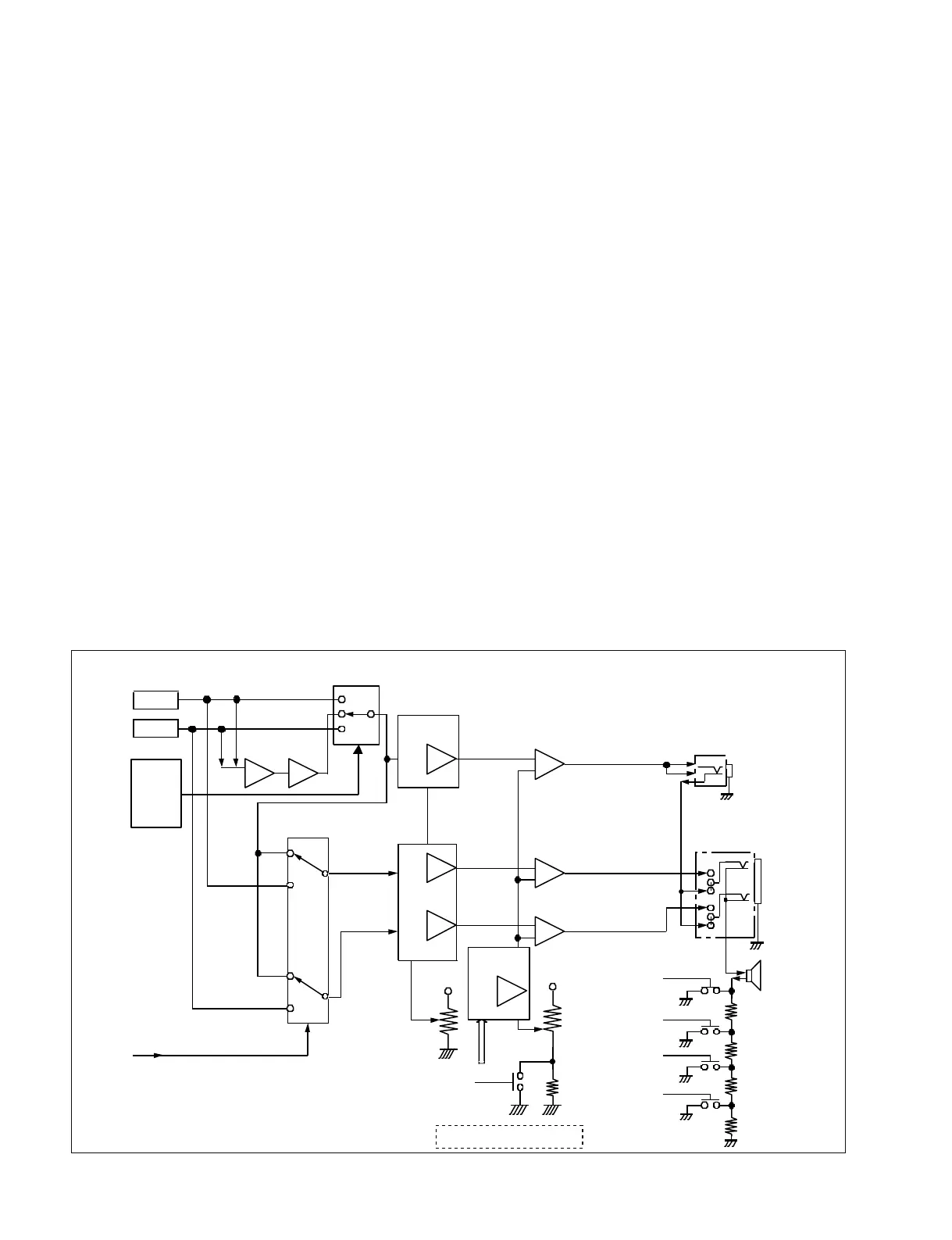
CH-1/3
CH-2/4
MIX INV
CH-1/3
CH-2/4
MIX
NJM-2172
+InA
_InA
Cont
Front_EARPHONE
L
R
L
R
+
_
+
_
+
_
+InB
_InB
+InA
_InA
Cont
NJM-2172
SW
FP-CPU(Head Phone Out:Streo/Mono)
REAR_EARPHONE
with SW
CH1&2
or
CH3&4
+3 Vdc
NJM386
NJM386
NJM386
VCA
VCA
MONITOR
SP
SW
SW
Final AMP
Final AMP
MONITOR-VR
ALARM-VR
FP_CPU
(SP ATT LEVEL:0dB)
FP_CPU
(SP ATT LEVEL:_3dB)
FP_CPU
(SP ATT LEVEL:_6dB)
FP_CPU
(SP ATT LEVEL:_9dB)
IC708
IC709
IC710
Q712
Q715
SW-1
SW-2
Q711
Q716
SW-3
Q713
Q717
SW-4
Q718
When ALARM-VOL Position 0 %,
Alarm Level is about _38 dBu.
IC707
IC706
IC750
OutB
OutA
OutA
FP_CPU (MIN ALARM VOL)
ALARM SIGNAL(FP_CPU)
CN701
CN702
CN703
RV700
RV701
R761
Q707
IC704
TC74HC4052
CH-1/3
CH-2/4
Streo
Streo
Mono
Mono
Final AMP
+InA
_InA
Cont
VCA
OutB
+3 Vdc
IC706
IC705
TC74HC4052
FP-CPU
(CH-1/3,
MIX,
CH-2/4)
Audio Monitor Block