1-9
PDW-700/V1 (E)
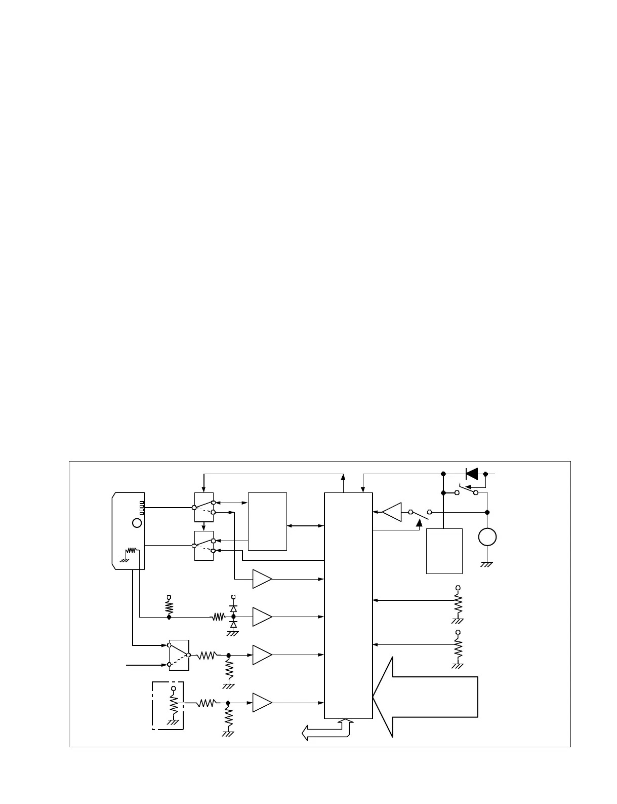
10. Info battery communication circuit.
This equipment supports batteries with SM Bus
specifications. The serial communication bus (SDA, SCL)
for IC916 (Parallel bus to I2C_bus Controller) connected
to the FP_CPU bus passes through IC927 and IC928
(switching switch) and connects to the serial terminal of
the info battery. The Serial Clock Rate is 88 KHz.
The battery type, remaining time, and other information is
loaded onto FP_CPU and transmitted to ITRON (CPU).
ITRON (CPU) calculates the remaining battery charge and
creates remaining charge display data, and transmits the
data to Camera CPU and FP_CPU. FP_CPU displays the
remaining charge display data on the monochrome LCD.
The remaining charge display data can be checked at the
same time in the status menu for the color LCD.
11. Power off software control circuit
FP_CPU detects the POWER-SW OFF information. When
power can be turned on, the "Power OFF" command is sent
from ITRON (CPU) and FP_CPU controls the power OFF
circuit on the CNB-25 board.
12. FP_CPU backup circuit
Even when power is turned off for FP_CPU, the data is
saved for the internal RAM and Real Time Clock (RX-
8025NB) through backup on a coin battery. By saving the
system data, FP_CPU can be started up quickly when the
power is turned on.
13. Backup lithium battery voltage measurement circuit
FP_CPU performs voltage measurement on the backup
lithium battery. When recharging is detected, the reduced-
voltage information is send to ITRON (CPU).
(Measurement interval time: 60 s)
Current is prevented from running through FET-SW
(Q836) in order to prevent power from being lost during
measurement. Furthermore, reverse current above +3 V is
prevented with FET-SW (Q829), thus extending the life of
the lithium battery. The battery life is guaranteed for about
5 years.
14. FP_CPU independent operations
When the POWER-SW is set to power off, power is
supplied from the UNSW +12 V power circuit to display
the counter and other information on the monochrome
LCD. Power is supplied to each power regulator with
IC830 (hyposaturation regulator 8 V) and independent
operations can be performed. The operations can be turned
on or off from the menu.
15. REAR input control
The serial communication bus (SDA, SCL) for IC917
(Parallel bus to I2C_bus Controller) connected to the
FP_CPU bus sends control for the AXM-38 board through
the motherboard with IC202 (PCA-9555: I2C_I/O_PORT)
on the CNB-25 board and acquires the following
information: REAR_XLR automatic insertion detection
D7
:
D0
SDA
PCA9564
HD64F2378
CLOCK 16 MHz
D15
:
D8
SCL
SW
INFO_ BATT
_SDA
INFO_BATT
_SCL
F
E
BATTERY
I2C_BUS
8 bit
CPU_BUS
Port
AN11
IC916
IC927
IC928
IC914
A
B
A
B
Port
Voltage
measurement
DC-in
Battery-in
FET-SW
(CNB-25 board)
UNREG+12 V
IC839
Voltage
measurement
AN13
IC838
Voltage
measurement
AN14
+3 V
Battery
ID Data
+3 V
Front
Microphone
Volume
SW-1425
Voltage
measurement
IC7
AN10
Voltage measurement
CH-2
RV2
Voltage measurement
CH-1
RV1
AN8
AN9
RX-8025NB
Real Time
Clock
Lithium
Coin
Battery
+3 V
FET-SW
Port
AN15
IC844
Q836
+3 V
(IC805)
to iTRON_CPU
IC921
CPU
IC908
(1 time/60 sec)
Battery
ID Register
+
Vcc
FET-SW
Q829
AN0
AN1
AN2
AN3
AN4
AN5
AN6
AN7
FRONT,REA,WRR-SW1,2,3,4
CTL,TC,U_BIT-SW
FREE,SET,REC_RUN-SW
PRESET,REGENE,CLOCK-SW
Monitor-SW
(3 digitize level)
+3 V
+5 V
+3 V
+3 V
Voltage Measurement Block Overview