RM0453 Rev 2 1121/1454
RM0453 Universal synchronous/asynchronous receiver transmitter (USART/UART)
1257
35.5 USART functional description
35.5.1 USART block diagram
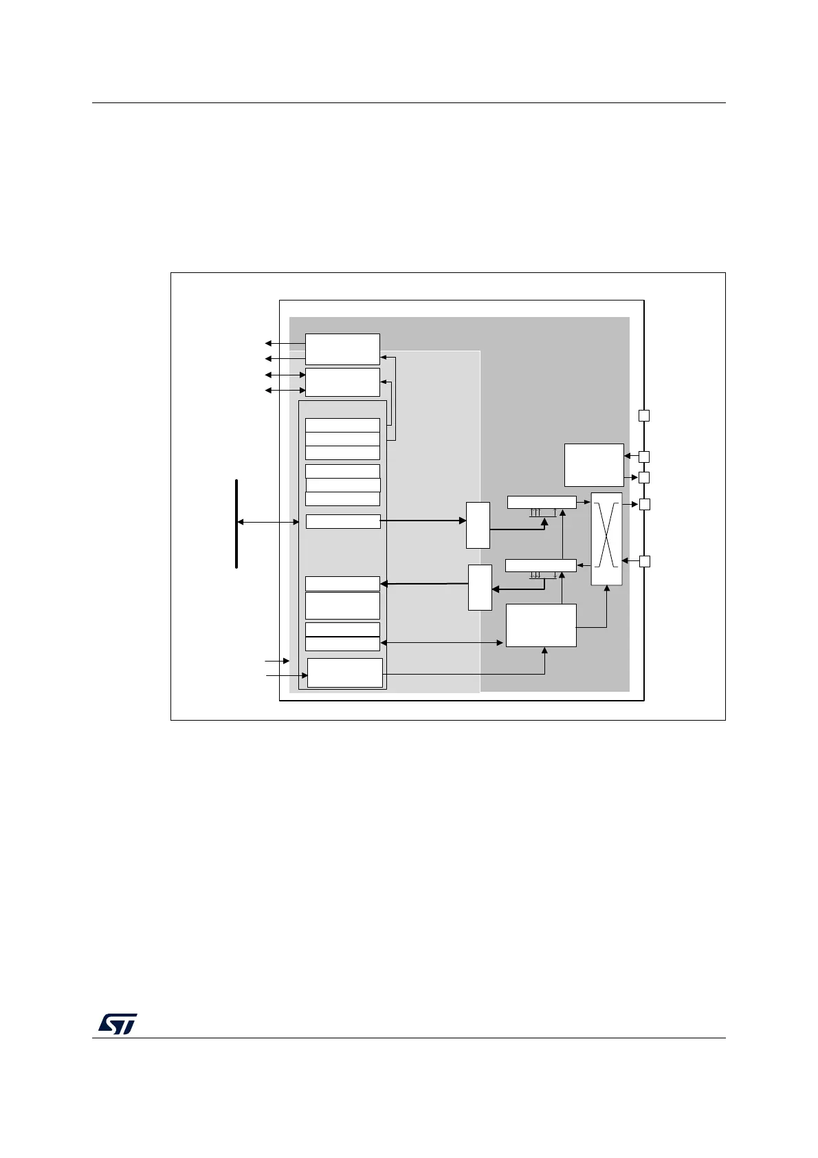
Figure 305. USART block diagram
The simplified block diagram given in Figure 305 shows two fully-independent clock
domains:
• The usart_pclk clock domain
The usart_pclk clock signal feeds the peripheral bus interface. It must be active when
accesses to the USART registers are required.
• The usart_ker_ck kernel clock domain.
The usart_ker_ck is the USART clock source. It is independent from usart_pclk and
delivered by the RCC. The USART registers can consequently be written/read even
when the usart_ker_ck clock is stopped.
When the dual clock domain feature is disabled, the usart_ker_ck clock is the same as
the usart_pclk clock.
There is no constraint between usart_pclk and usart_ker_ck: usart_ker_ck can be faster
or slower than usart_pclk. The only limitation is the software ability to manage the
communication fast enough.
3. Wakeup supported from Stop 0, Stop 1 and Stop 2 modes.
MSv40854V3
USART_TDR
USART_RDR
USART_GTPR
USART_BRR
USART_CR3
USART_RQR
USART_CR2
RX Shift Reg
COM Controller
RxFIFO
usart_pclk
clock domain
USART
TX
RX
usart_ker_ck
32-bit APB bus
USART_ICR
USART_ISR
...
TX Shift Reg
...
CTS/NSS
RTS/DE
USART_CR1
USART_
RTOR
Baudrate
generator &
orversampling
usart_ker_ck clock domain
DMA Interface
usart_pclk
usart_tx_dma
usart_rx_dma
usart_it
usart_wkup
IRQ Interface
CK
USART_
PRESC
usart_ker_ck_pres
Hardware
flow control
TxFIFO

 Loading...


