Reset and clock control (RCC) RM0453
290/1454 RM0453 Rev 2
7.2.14 ADC clock
The ADC clock is derived from the system clock, from the HSI16 clock, or from the PLL
output. The ADC clock can reach 35 MHz and can be divided by the following prescalers
values: 1, 2, 4, 6, 8, 10, 12, 16, 32, 64, 128 or 256 by configuring the ADC_CCR register. It
is asynchronous to the AHB clock. Alternatively, the ADC clock can be derived from the AHB
clock of the ADC bus interface, divided by a programmable factor (1, 2 or 4). This
programmable factor is configured using the CKMODE bit fields in the ADC_CCR register.
If the programmed factor is 1, the AHB prescaler must be set to 1.
7.2.15 RTC clock
The RTCCLK clock source can be either the HSE32 divided by 32, the LSE or the LSI clock.
RTCCLK is selected by programming the RTCSEL[1:0] bits in the RCC Backup domain
control register (RCC_BDCR). This selection cannot be modified without resetting the
Backup domain. The system must always be configured so as to get a PCLK frequency
greater then or equal to the RTCCLK frequency for a proper operation of the RTC.
The LSE clock is in the Backup domain, whereas the HSE32 and LSI clocks are not, with
the following consequences:
• If LSE is selected as RTC clock, the RTC continues to work even if the V
DD
supply is
switched off, provided the V
BAT
supply is maintained.
• If LSI is selected as the RTC clock, the RTC state is not guaranteed if the V
DD
supply is
powered off.
• If the HSE32 clock divided by a prescaler is used as the RTC clock, the RTC state is
not guaranteed if the V
DD
supply is powered off or if the internal voltage regulator is
powered off (removing power from the V
CORE
domain).
When the RTC clock is LSE or LSI, the RTC remains clocked and functional under system
reset.
7.2.16 Timer clock
The timer clock frequencies are automatically defined by hardware.
The following cases are possible:
• If the APB prescaler (PPREx) selects the PCLKx clock to be HCLK1 not divided, the
timer clock frequencies are set to the HCLK1 frequency (timer clock = HCLK1).
• If the APB prescaler (PPREx) selects the PCLKx clock to be HCLK1 divided by n, the
timer clock frequencies are set to HCLK1 divided by (n / 2) (timer clock = 2 x PCLKx).
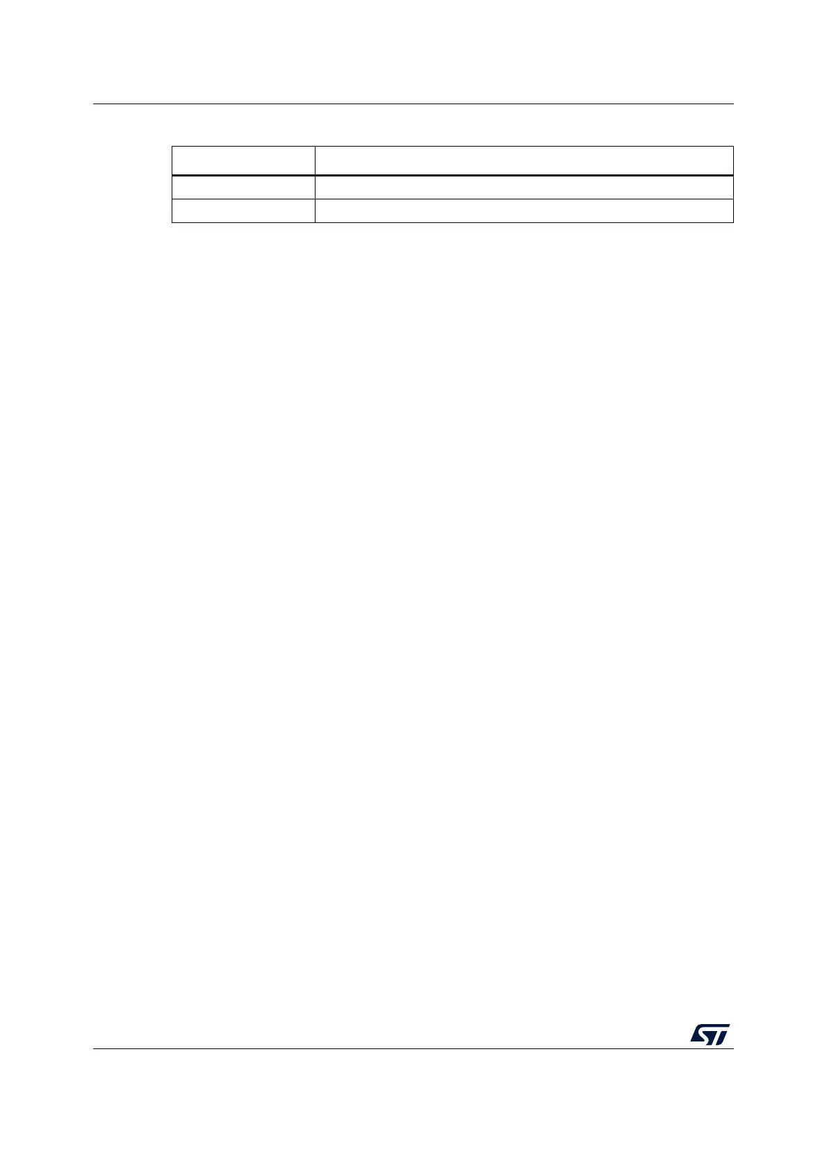
Table 60. Sub-GHz radio SPI clock configurations
PCLK3 [MHz] SUBGHZSPI_SCK clock maximum speed
48 PCLK / 4
(1)
= 12 MHz
1. As controlled by SUBGHZSPI_CR1 BR baud rate control.
32 PCLK / 2
(1)
= 16 MHz

 Loading...


