Digital-to-analog converter (DAC) RM0453
598/1454 RM0453 Rev 2
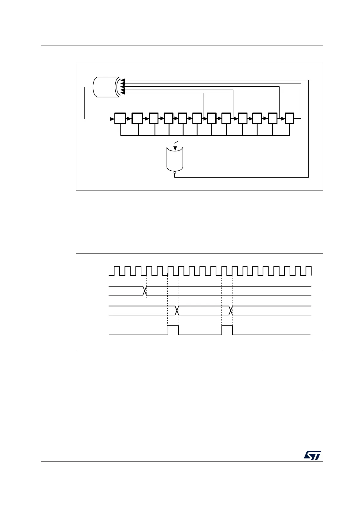
Figure 89. DAC LFSR register calculation algorithm
The LFSR value, that may be masked partially or totally by means of the MAMP1[3:0] bits in
the DAC_CR register, is added up to the DAC_DHR1 contents without overflow and this
value is then transferred into the DAC_DOR1 register.
If LFSR is 0x0000, a ‘1 is injected into it (antilock-up mechanism).
It is possible to reset LFSR wave generation by resetting the WAVE1[1:0] bits.
Figure 90. DAC conversion (SW trigger enabled) with LFSR wave generation
Note: The DAC trigger must be enabled for noise generation by setting the TEN1 bit in the
DAC_CR register.
11 10 9 8 7 6 5 4 3 2 1 0
12
NOR
X
12
X
0
X
X
4
X
6
XOR
ai14713c
dac_pclk
0x00
0xAAA
DHR
DOR
MS45320V1
0xD55
SWTRIG

 Loading...


