Comparator (COMP) RM0453
622/1454 RM0453 Rev 2
21.3 COMP functional description
21.3.1 COMP block diagram
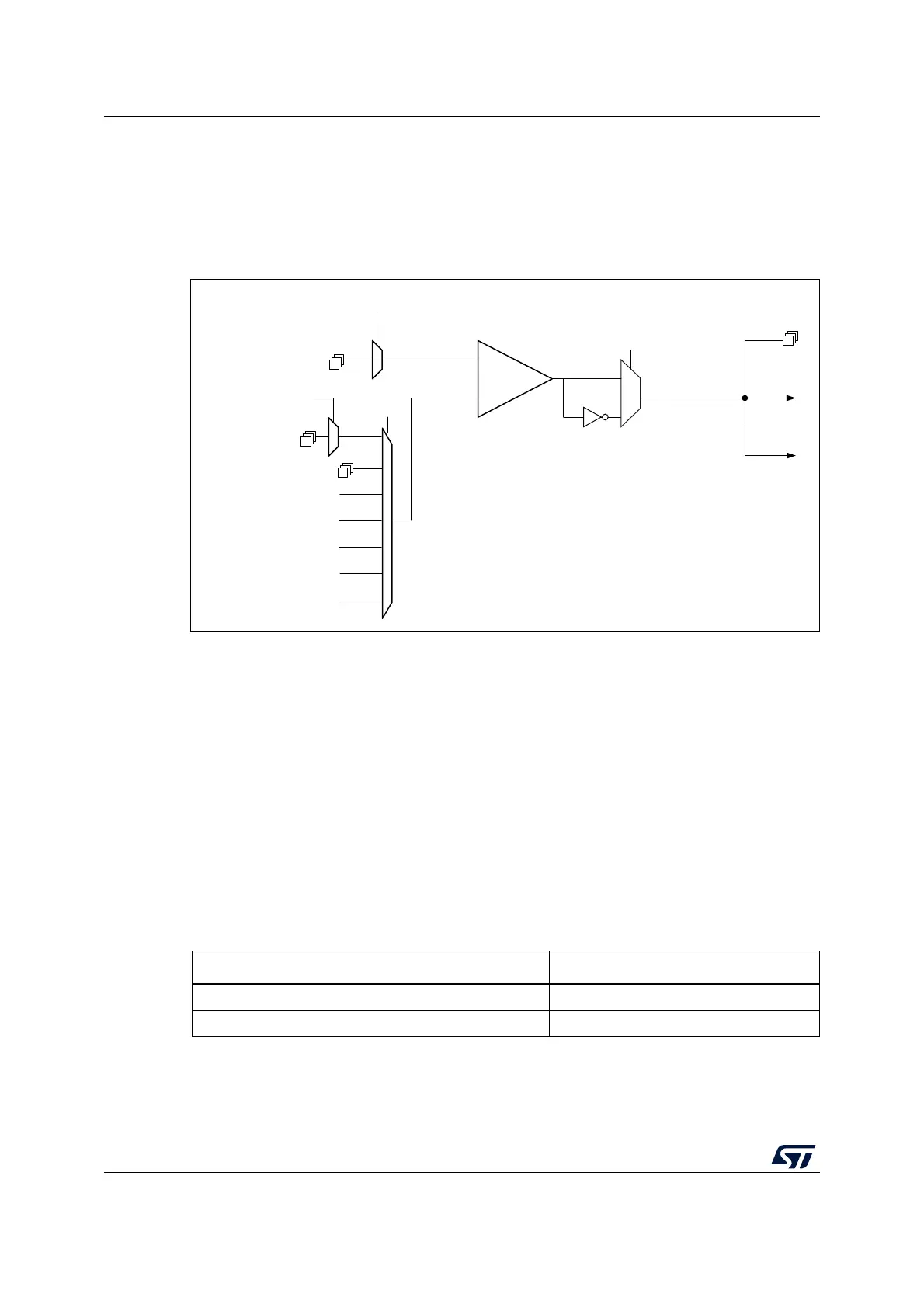
The block diagram of the comparators is shown in the figure below.
Figure 94. Comparator block diagram
21.3.2 COMP pins and internal signals
The I/Os used as comparator inputs must be configured in analog mode in the GPIO
registers.
The comparator outputs can be connected to the I/Os through their alternate functions (refer
to the product datasheet).
The outputs can also be internally redirected to a variety of timer inputs for the following
purposes:
• emergency shut-down of PWM signals, using BKIN and BKIN2 inputs
• cycle-by-cycle current control, using OCREF_CLR inputs
• input capture for timing measurements
The comparator output can be simultaneously redirected internally and externally.
MSv60765V1
COMPx_INM I/Os
COMPx_INP I/Os
1/4 V
REFINT
3/4 V
REFINT
1/2 V
REFINT
V
REFINT
COMPx_INP
COMPx_INM
Polarity
selection
COMPx_POL
COMPx_VALUE
COMPx_
INMSEL
GPIO alternate
function
+
-
COMPx
COMPx_INPSEL
COMPx_INM I/Os
COMPx_INMESEL
COMPx_OUT
Wakeup EXTI
line interrupt
Timers
DAC_CH1
Table 122. COMP1 input plus assignment
COMP1_INP COMP1_INPSEL
PB4 00
PB2 01

 Loading...


