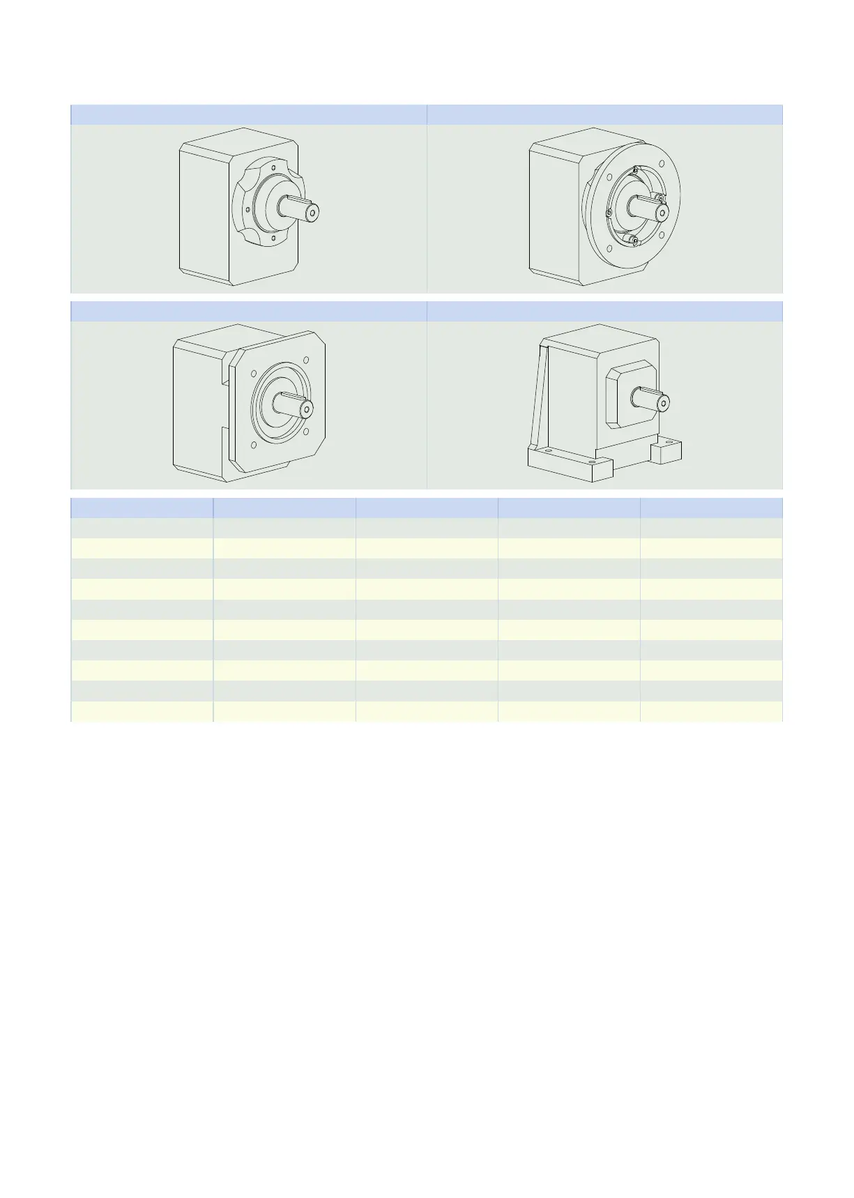
5.5.3 Housing design
Pitch circle diameter G Round flange F
Square flange Q Foot N
G F Q N
C0 ✓ ✓ ✓ ✓
C1 ✓ ✓ ✓ ✓
C2 ✓ ✓ ✓ ✓
C3 ✓ ✓ ✓ ✓
C4 ✓ ✓ ✓ ✓
C5 ✓ ✓ − ✓
C6 ✓ ✓ − ✓
C7 ✓ ✓ − ✓
C8 ✓ ✓ − ✓
C9 ✓ ✓ − ✓
5.5.4 Shaft design
Gear units in sizes C0 – C9 come standard with a solid shaft with feather key.
Gear units in sizes C0 – C5 can be ordered with the option of a solid shaft without feather key. Only upon re-
quest starting at size C6.
5.5.5 Installation conditions
Fastening the gear units on the machine side using the pitch circle diameter
The specified torques and forces only apply when gear units are fastened on the machine side using screws
of strength class 10.9. In addition, the gear housings must be adjusted at the pilot. The machine-side fit
must be H7.
5 Chelical geared motors 5.5 Product description
125