Technical data for operation with high-speed rectifier 104VDC (supply voltage U
LINE
220 – 275VAC ± 5%, 50/60Hz)
Type M
1Bstat
J
1
m Δφ
B
t
1B,DC
t
1B,AC
t
2B
P
O,B
P
holdB
[Nm] [kgcm²] [kg] [arcmin] [ms] [ms] [ms] [W] [W]
MB23 8.0 6.3 8.5 32.0 65 360 20 101 26
MB23 12 6.3 8.5 32.0 55 280 25 101 26
MB23 16 6.3 8.5 32.0 50 230 35 101 26
MB23 24 6.3 8.5 32.0 45 180 50 101 26
MB23 30 6.3 8.5 32.0 40 160 60 101 26
MB33 16 26 14 26.0 150 800 25 125 32
MB33 24 26 14 26.0 120 650 35 125 32
MB33 32 26 14 26.0 95 500 40 125 32
MB33 45 26 14 26.0 80 400 50 125 32
MB33 90 26 14 26.0 50 250 90 125 32
MB43 50 69 26 19.0 150 900 50 148 38
MB43 72 69 26 19.0 120 700 75 148 38
MB43 100 69 26 19.0 90 500 100 148 38
MB43 160 69 26 19.0 60 300 150 148 38
MB53 200 236 61 17.0 200 800 110 200 50
MB53 300 236 61 17.0 170 600 150 200 50
MB53 400 236 61 17.0 120 400 200 200 50
Δφ
B
: With the brake closed, a higher total backlash results (Δφ
tot
= Δφ
2
+ Δφ
B
/ i).
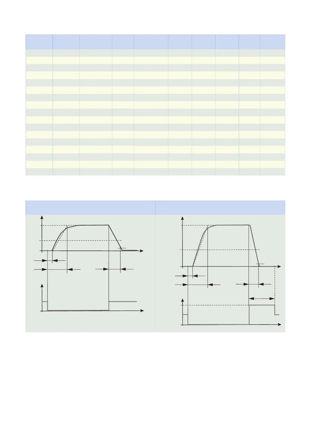
4.5.2.6 Brake switching times
Switching times in case of brake operation with nominal voltage Switching times in case of brake operation with overexcitation volt-
age
t11B
t1B
t2B
0,1 x M1Bstat
M1Bstat
M
ML*
U
UN,B
t
t
t11B
t1B
t2B
0,1 x M1Bstat
M1Bstat
M
U
UholdB = UN,B
t
t
UO,B
tO,B
ML*
4.5.3 Installation conditions
The torque and force values listed in this catalog are valid under the following conditions:
• When the flange shaft and gear housing are fastened on the machine side using screws of strength class
12.9
• When the gear housings are adjusted at pilot øb1, and also at pilot Øb for size PHQ11. The machine-
side fit must be H7.
• When the flange shaft is adjusted using the connecting element at pilot øbf or ødf
4 PHQplanetary geared motors 4.5 Product description
73