Technical data
Motor Forced venti-
lation unit
U
N,F
[V]
I
N,F
[A]
P
N,F
[W]
q
vF
[m³/h]
L
pA,F
[dBA]
m
F
[kg]
Protection
class
EZ4_B FL4
230 V ± 5%,
50/60Hz
0.07 10 59 41 1.4 IP44
EZ5_B FL5 0.10 14 160 45 1.9 IP54
EZ7_B FL7 0.10 14 160 45 2.9 IP54
EZ8_B FL8 0.20 26 420 54 5.0 IP55
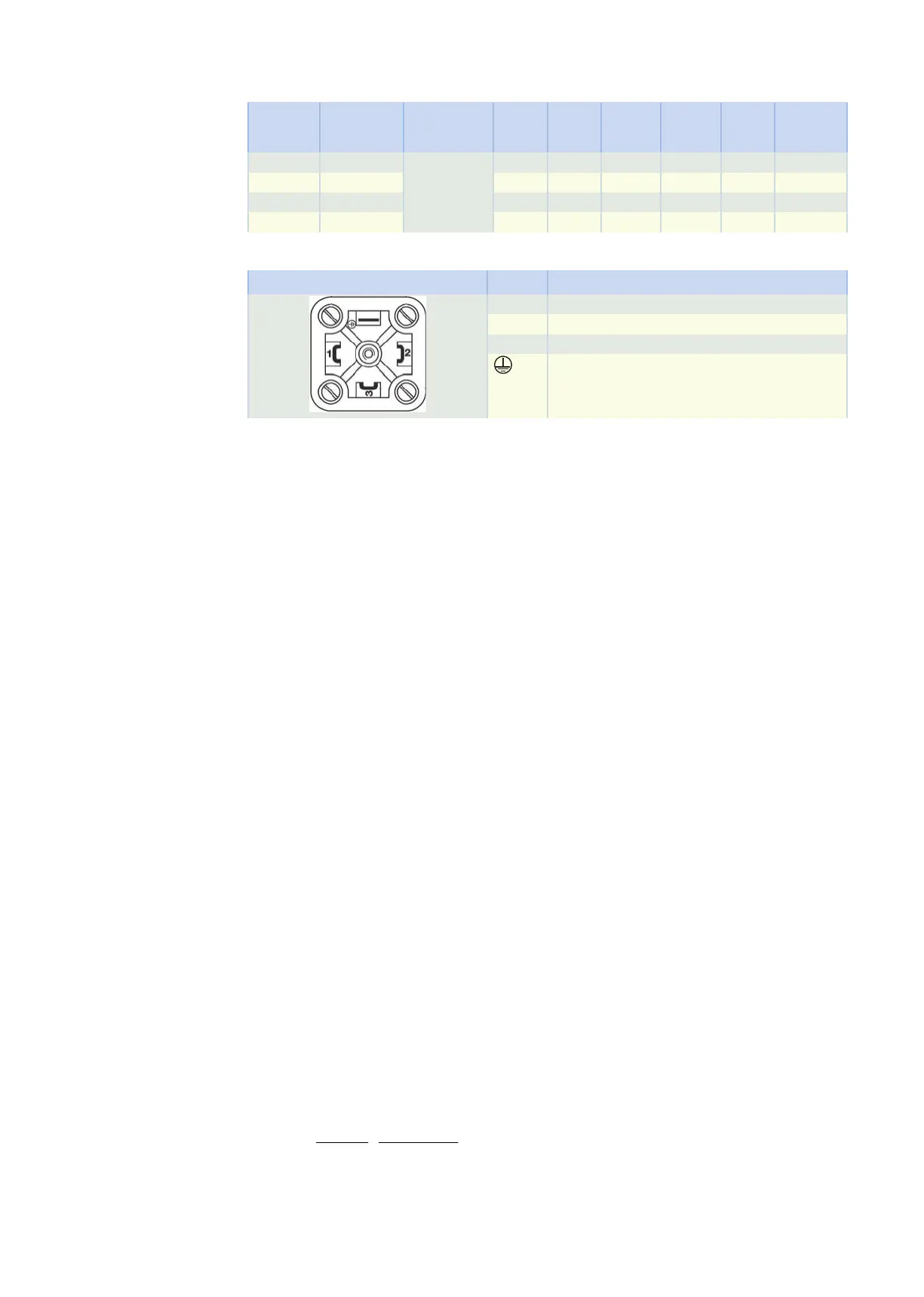
Terminal assignment for forced ventilation unit plug connectors
Connection diagram Pin Connection
1 L1 (phase)
2 N (neutral conductor)
3
Grounding conductor
11.6.7 Holding brake
STOBER synchronous servo motors can be equipped with a backlash-free holding brake using permanent
magnets in order to secure the motor shaft when at a standstill. The holding brake engages automatically if
the voltage drops.
The holding brake is designed for a high number of operations (B
10
= 10 million operations, B
10d
= 20 million
operations).
Nominal voltage of permanent magnet holding brake: DC 24V ± 5%, smoothed.
Observe the following during project configuration:
• The holding brake is designed to keep the motor shaft from moving. Activate braking processes during
operation using the corresponding electrical functions of the drive controller. In exceptional circum-
stances, the holding brake can be used for braking from full speed (following a power failure or when
setting up the machine). The maximum permitted work done by friction W
B,Rmax/h
may not be exceeded.
• Note that the braking torque M
Bdyn
may initially be up to 50% less when braking from full speed. As a re-
sult, the braking effect has a delayed action and braking distances become longer.
• Regularly perform a brake test to ensure the functional safety of the brakes. Details can be found in the
documentation of the motor and the drive controller.
• Connect a varistor of type S14 K35 (or comparable) in parallel to the brake coil to protect your machine
from switching surges. (Not necessary for connecting the holding brake to STOBER drive controllers of
the 5th and 6th generation with a BRS/BRM brake module).
• The holding brake of the motor does not offer adequate safety for persons in the hazardous area of
gravity-loaded vertical axes. Therefore take additional measures to minimize risk, e.g. by providing a
mechanical substructure for maintenance work.
• Take into consideration voltage losses in the connection cables that connect the voltage source to the
holding brake connections.
• The holding torque of the brake can be reduced by shock loading. Information about shock loading can
be found in the "Ambient conditions" chapter.
• At operating temperatures from −15°C to 0°C, a cold holding brake in the released state may cause op-
erating noises. As the temperature of the holding brake increases, these noises decrease such that op-
erating noises are not heard when using holding brake at operating temperature in the released state.
Calculation of work done by friction per braking process
×
= × >
±
2
Bdyn
tot
B,R/B Bdyn L
Bdyn L
M
J n
W , M M
182.4 M M
The sign of M
L
is positive if the movement runs vertically upwards or horizontally and it is negative if the
movement runs vertically down.
11 EZsynchronous servo motors 11.6 Product description
403