10.5.4 Combinatorial shaft/housing design
Housing design
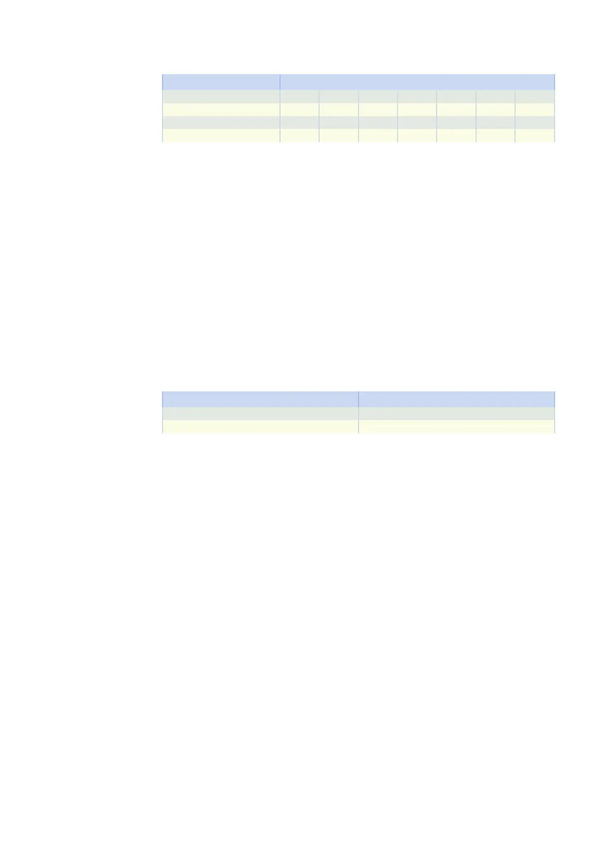
Shaft design Code G F NG NF GD NGD
Hollow shaft with keyway A AG AF ANG ANF AGD ANGD
Hollow shaft with shrink ring S SG SF SNG SNF SGD SNGD
Solid shaft
1)
V VG VF VNG VNF − −
1)
Gear units in sizes K1 – K10 come with a solid shaft with feather key as standard. Gear units in sizes K1 –
K4 can be ordered with the option of a solid shaft without feather key. Only upon request starting at size K5.
10.5.5 Installation conditions
Hollow shaft
The hollow shaft hole tolerance is ISO H7. The tolerance of the machine shaft must be ISO k6.
Take care to align the machine shaft with the gear unit hollow shaft when attaching the gear unit.
Maximum deviation ≤ 0.03 mm.
For simpler assembly and disassembly of the machine shaft, the hollow shafts are equipped with a spiral
groove (as a grease deposit).
A hardened, threaded keeper plate is included in the scope of delivery. You also have the option to order
the hollow shaft without a keeper plate.
Hollow shaft with shrink ring
The tolerance of the hollow shaft hole is ISO H7.
The machine shaft must be executed as follows:
Gear unit type Tolerance
K1 to K6 ISO h9
K7 to K10 ISO h6
Select a material for the machine shaft with a permitted surface pressure of p ≥ 325 N/mm
2
.
Possible materials:
• C45E +QT
• 42CrMo4
Fastening the gear units on the machine side using the pitch circle diameter
The specified torques and forces only apply when gear units are fastened on the machine side using screws
of strength class 10.9. In addition, the gear housings must be adjusted at the pilot. The machine-side fit
must be H7.
10.5.6 Mounting positions
The following table shows the standard mounting positions.
The numbers identify the gear unit sides. The mounting position is defined by the gear side facing down-
wards.
10 Khelical bevel geared motors 10.5 Product description
359