13.7 Connection to Allen-Bradley drive controllers
This chapter contains the information for connecting STOBER synchronous servo motors to drive controllers
of the above-named manufacturer which differs from connecting to STOBER drive controllers. You can find
all other information about STOBER synchronous servo motors in the respective chapter of this catalog.
The following STOBER series can be configured to Kinetix 5500/5700/6500 drive controllers fully automati-
cally: EZ geared motors; EZHD, EZM, EZS motors. This does not include EZ motors without an attached gear
unit and other STOBER series.
STOBER has taken the following measures to minimize the effort of commissioning STOBER motors con-
nected to Allen-Bradley drive controllers and avoid errors during parameterization:
• The commutation offset of the motor was set so that calibration by the customer is not necessary.
• The electronic nameplate of the motor was designed to be compatible with the Kinetix
5500/5700/6500.
• STOBER tests the motor connected to Allen-Bradley drive controllers before delivery to the customer.
• Configuration files for supported motor versions are available for download.
13.7.1 Encoders
Encoders with EnDat 2.2 interface
Encoder model Code Measur-
ing
method
Recordable
revolutions
Resolu-
tion
Position values
per revolution
MTTF
[years]
PHF [h]
EnDat 2.2 EQN 1135 Q5 Optical 4096 23 bit 8388608 > 100 ≤15×10
-9
EnDat 2.2 ECI 119-G2 C9 Inductive – 19 bit 524288 > 57 ≤2×10
-6
Encoders with HIPERFACE interface
Encoder model Code Measur-
ing
method
Recordable
revolutions
Resolu-
tion
Position values
per revolution
MTTF
[years]
PHF [h]
EDM35 H6 Optical 4096 20 bit 1048576 > 100 ≤31×10
-9
Notes
• The encoder code is a part of the type designation of the motor.
• Multiple revolutions of the motor shaft can be recorded only using multi-turn encoders.
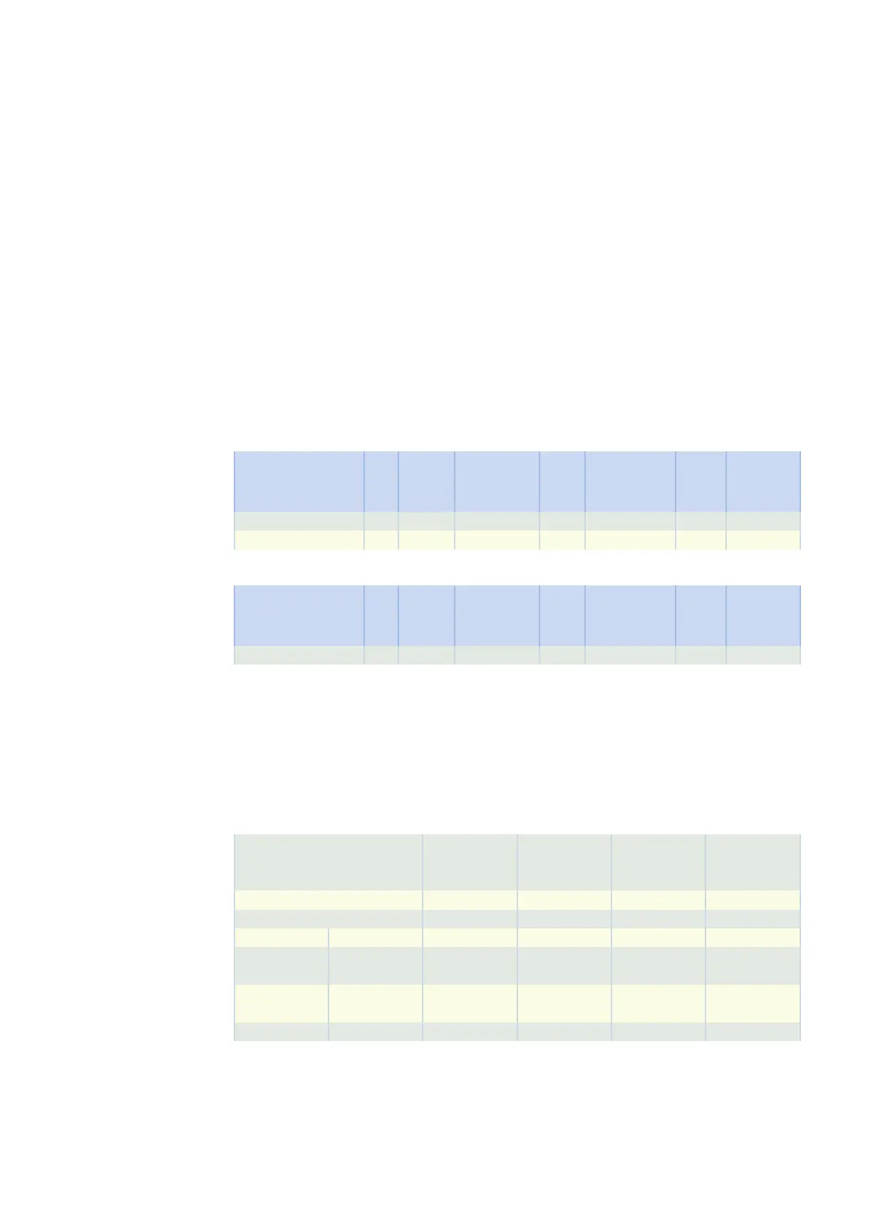
13.7.2 Possible combinations with drive controllers
The following table shows the possible combinations of STOBER motors and geared motors with drive con-
trollers from Allen-Bradley depending on the encoder model.
Drive controller KINETIX 5500
(with HIPERFACE
DSL)
KINETIX 5700
(with HIPERFACE
DSL)
KINETIX 5700
(with EnDat 2.2)
KINETIX 6500
(with EnDat 2.2)
Drive controller code HB GD HA GC
Connection plan ID 443169 442449 443096 442448
Encoder Encoder code
EnDat 2.2 EQN
1135
Q5 – – EZ, EZS EZ, EZS
EnDat 2.2 ECI
119-G2
C9 – – EZHD, EZM EZHD, EZM
EDM35 H6 EZ, EZS EZ, EZS – –
The encoder and drive controller codes are a part of the type designation of the motor.
13.7.3 Terminal assignment of the power plug connector
The size and connection plan of the power plug connector depend on the size of the motor. The colors of
the connecting wires inside the motor are specified in accordance with IEC 60757.
13.7 Connection to Allen-Bradley drive controllers 13 Connecting to drive controllers of third-party manufac-
turers
442