7.3 Dimensional drawings
In this chapter, you can find the dimensions of the geared motors with redundant brake.
There is a dimensional drawing for every possible shaft/housing design, each with the tables for gear unit di-
mensions, motor adapter dimensions, motor dimensions and geared motor dimensions.
Dimensions can exceed the specifications of ISO 2768-mK due to casting tolerances or accumulation of indi-
vidual tolerances.
We reserve the right to make dimensional changes due to ongoing technical development.
You can download 3D models of our standard drives at https://configurator.stoeber.de/en-US/
.
Combination options and the dimensions of forced ventilated geared motors can also be found at https://
configurator.stoeber.de/en-US/.
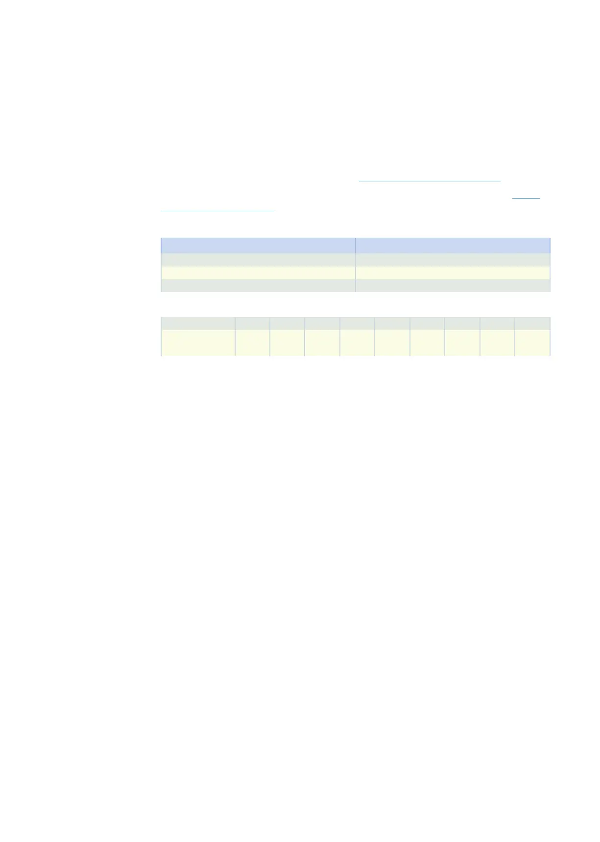
Tolerances
Solid shaft Tolerance
Fit ISO k6
Feather keys DIN 6885-1, high form A
Balancing With half feather key
Centering holes in solid shafts in accordance with DIN 332-2, DR shape
Thread size M4 M5 M6 M8 M10 M12 M16 M20 M24
Thread depth
[mm]
10 12.5 16 19 22 28 36 42 50
7 PKright-angle planetary geared motors 7.3 Dimensional drawings
201