11.4 Dimensional drawings
In this chapter, you can find the dimensions of the motors.
Dimensions can exceed the specifications of ISO 2768-mK due to casting tolerances or accumulation of indi-
vidual tolerances.
We reserve the right to make dimensional changes due to ongoing technical development.
You can download 3D models of our standard drives at https://configurator.stoeber.de/en-US/
.
Tolerances
Solid shaft Tolerance
Shaft ∅ fit ≤ 50 mm DIN 748-1, ISO k6
Shaft ∅ fit > 50 mm DIN 748-1, ISO m6
Centering holes in solid shafts in accordance with DIN 332-2, DR shape
Thread size M4 M5 M6 M8 M10 M12 M16 M20 M24
Thread depth
[mm]
10 12.5 16 19 22 28 36 42 50
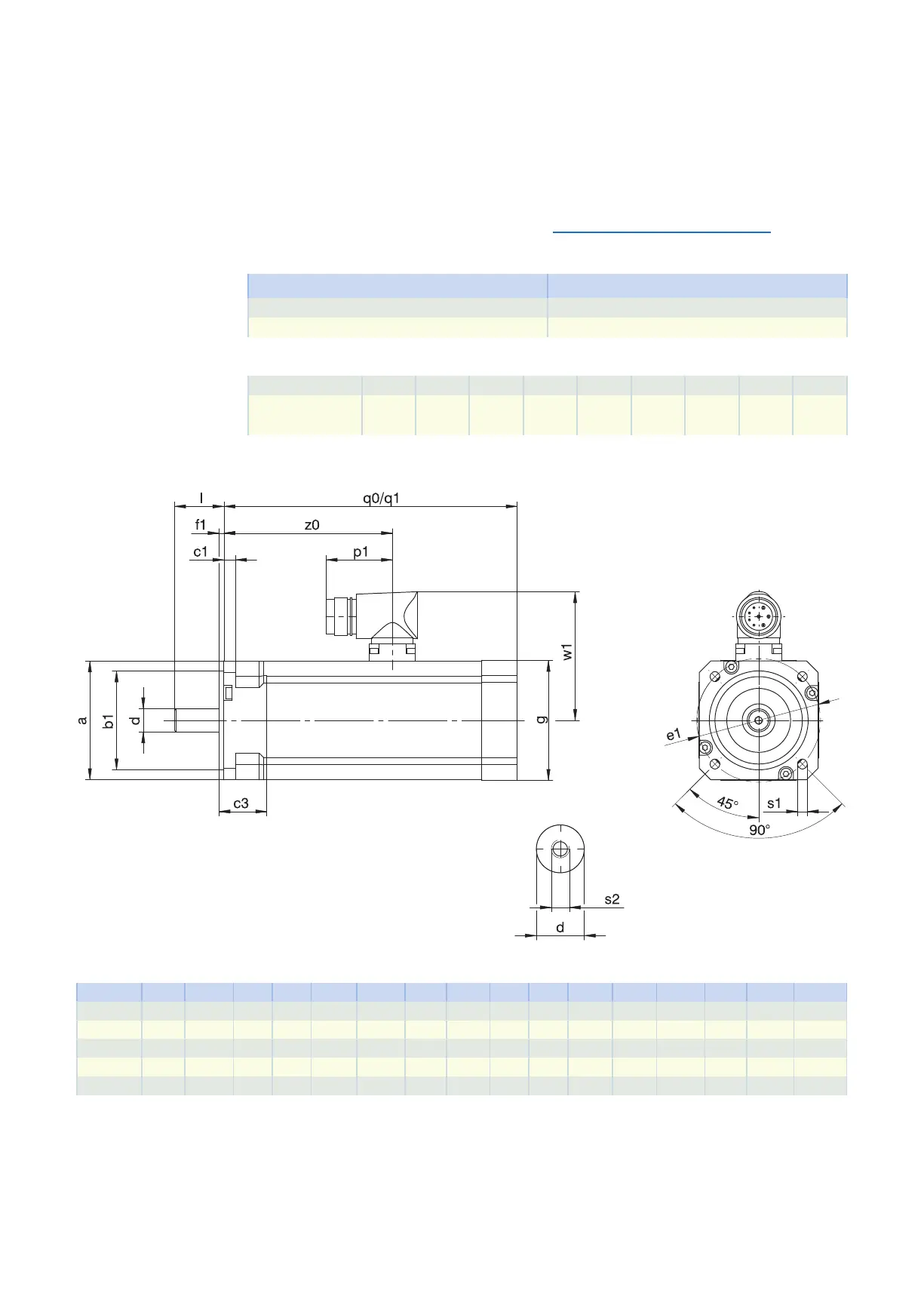
11.4.1 EZ2 – EZ3 motors (One Cable Solution)
q0 Applies to motors without holding brake q1 Applies to motors with holding brake
Type
☐
a
∅
b1
c1 c3
∅
d
∅
e1
f1
☐
g
l p1 q0 q1
∅
s1
s2 w1 z0
EZ202U 55 40
j6
7 7 9
k6
63 3.5 55 20 40 148 157 5.8 M4 69.5 93.0
EZ203U 55 40
j6
7 7 9
k6
63 3.5 55 20 40 166 175 5.8 M4 69.5 111.0
EZ301U 72 60
j6
7 26 14
k6
75 3.0 72 30 40 116 156 6.0 M5 78.0 80.5
EZ302U 72 60
j6
7 26 14
k6
75 3.0 72 30 40 138 178 6.0 M5 78.0 102.5
EZ303U 72 60
j6
7 26 14
k6
75 3.0 72 30 40 160 200 6.0 M5 78.0 124.5
11.4 Dimensional drawings 11 EZsynchronous servo motors
390