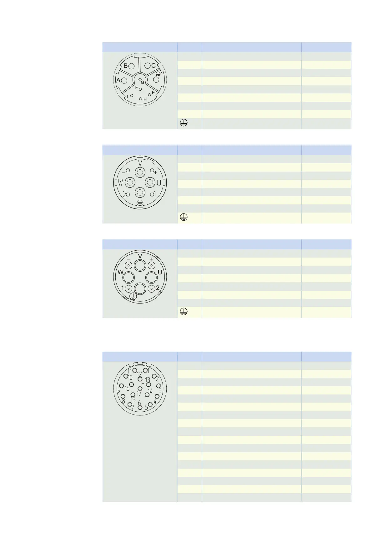
Plug connector size con.23
Connection diagram Pin Connection Color
A 1U1 (U phase) BK
B 1V1 (V phase) RD
C 1W1 (W phase) BU
F MBRK + (1BD1) RD
G MBRK − (1BD2) BK
E
H
L
PE (grounding conductor) GNYE
Plug connector size con.40 (1.5)
Connection diagram Pin Connection Color
U 1U1 (U phase) BK
V 1V1 (V phase) BU
W 1W1 (W phase) RD
+ MBRK + (1BD1) RD
− MBRK − (1BD2) BK
1
2
PE (grounding conductor) GNYE
Plug connector size con.58 (3)
Connection diagram Pin Connection Color
U 1U1 (U phase) BK
V 1V1 (V phase) BU
W 1W1 (W phase) RD
+ MBRK + (1BD1) RD
− MBRK − (1BD2) BK
1
2
PE (grounding conductor) GNYE
13.7.4 Terminal assignment of the encoder plug connector
EnDat 2.2 digital encoder, plug connector size con.23
Connection diagram Pin Connection Color
1
2
3
4
5 DATA + GY
6 DATA – PK
7 CLK + (Clock +) VT
8 CLK – (Clock –) YE
9 EPWR_5V (Up +) BNGN
10 ECOM (0V) WHGN
11
12
13 TS + (1TP1) BK
14 TS – (1TP2) WH
15
16
17
13 Connecting to drive controllers of third-party manufacturers 13.7 Connection to Allen-Bradley drive con-
trollers
443