5.6.2 Permitted shaft loads for the output shaft
The values specified in the tables apply to the permitted shaft loads:
• For shaft dimensions in accordance with the catalog
• For output speeds n
2m*
≤ 20 rpm (F
2axN
= F
2ax20
; F
2radN
= F
2rad20
; M
2kN
= M
2k20
)
• Only if radial forces on the gear unit are stabilized by its pilots for the pitch circle diameter and flange
housing design
Permitted shaft loads
Type z
2
F
2ax20
F
2rad20
F
2rad,acc
M
2k20
M
2k,acc
[mm] [N] [N] [N] [Nm] [Nm]
C0 20.0 500 1900 1900 80 80
C1 30.0 850 3400 3400 190 190
C2 30.0 1050 4200 4200 260 260
C3 30.0 1400 5650 5650 350 350
C4 35.0 2400 9700 9700 750 750
C5 42.0 3000 11000 11000 900 900
C6 40.0 4000 16000 16000 1500 1500
C7 45.0 5500 22000 22000 2400 2400
C8 50.0 7500 30000 30000 3700 3700
C9 55.0 9500 37000 37000 5200 5200
For other output speeds, download diagrams at https://configurator.stoeber.de/en-US/
.
The following applies to output speeds n
2m*
> 20 rpm:
2ax 20
2axN
2m*
3
1
F
F
n
20min
-
=
2rad20
2radN
2m*
3
1
F
F
n
20min
-
=
The values for F
2ax20
, F
2rad20
and M
2k20
can be found in the table "Permitted shaft loads" in this chapter.
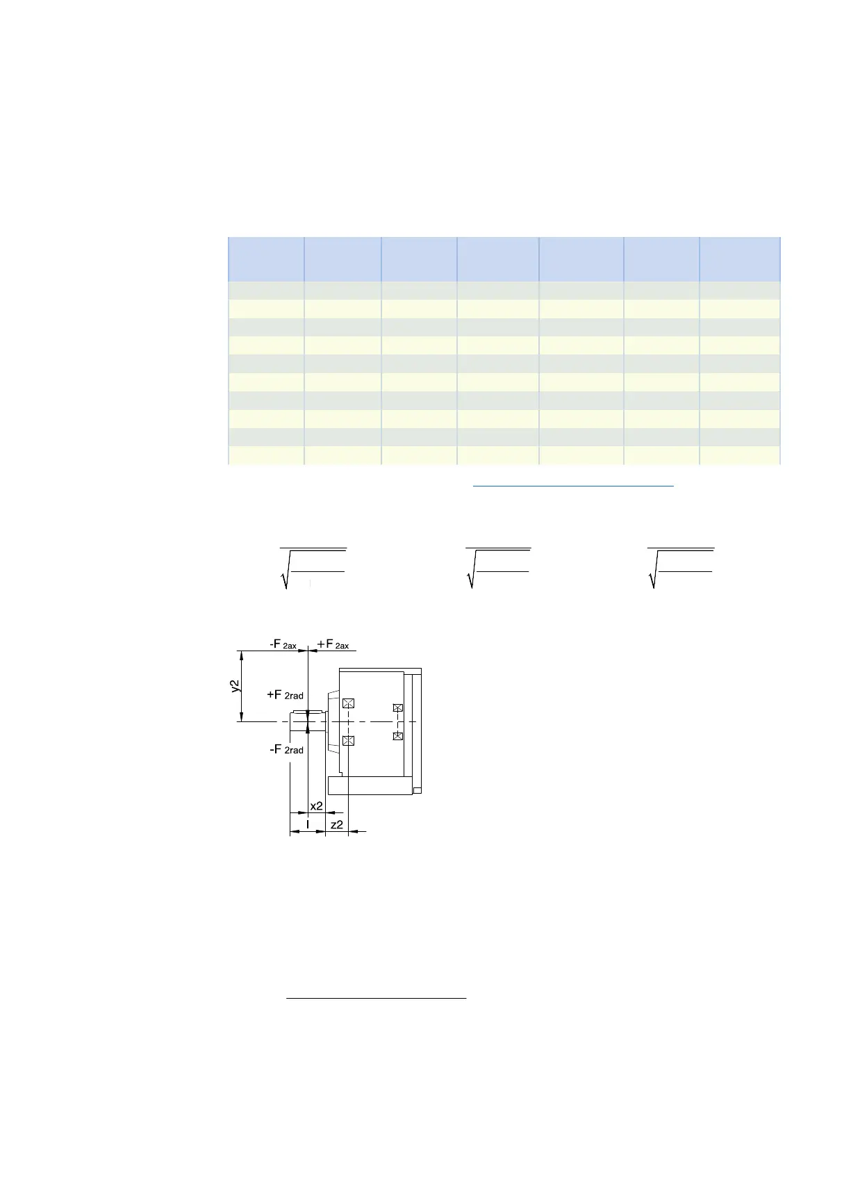
Fig.2: Force application points
The specified values for F
2rad20
and F
2rad,acc
refer to an application of force at the center of the output shaft: x
2
= l/2.
Shaft dimensions can be found in the "Dimensional drawings" chapter.
The following applies to other force application points:
( )
× × + × +
=
2ax * 2 2rad,acc* 2 2
2k,acc*
2 F y F x z
M
1000
For applications with multiple axial and/or radial forces, you must add the forces as vectors.
In the event of EMERGENCY OFF operation (max. 1000 load changes), you can multiply the permitted forces
and torques for F
2ax20
, F
2rad20
and M
2k20
by a factor of two.
5.6 Project configuration 5 Chelical geared motors
134