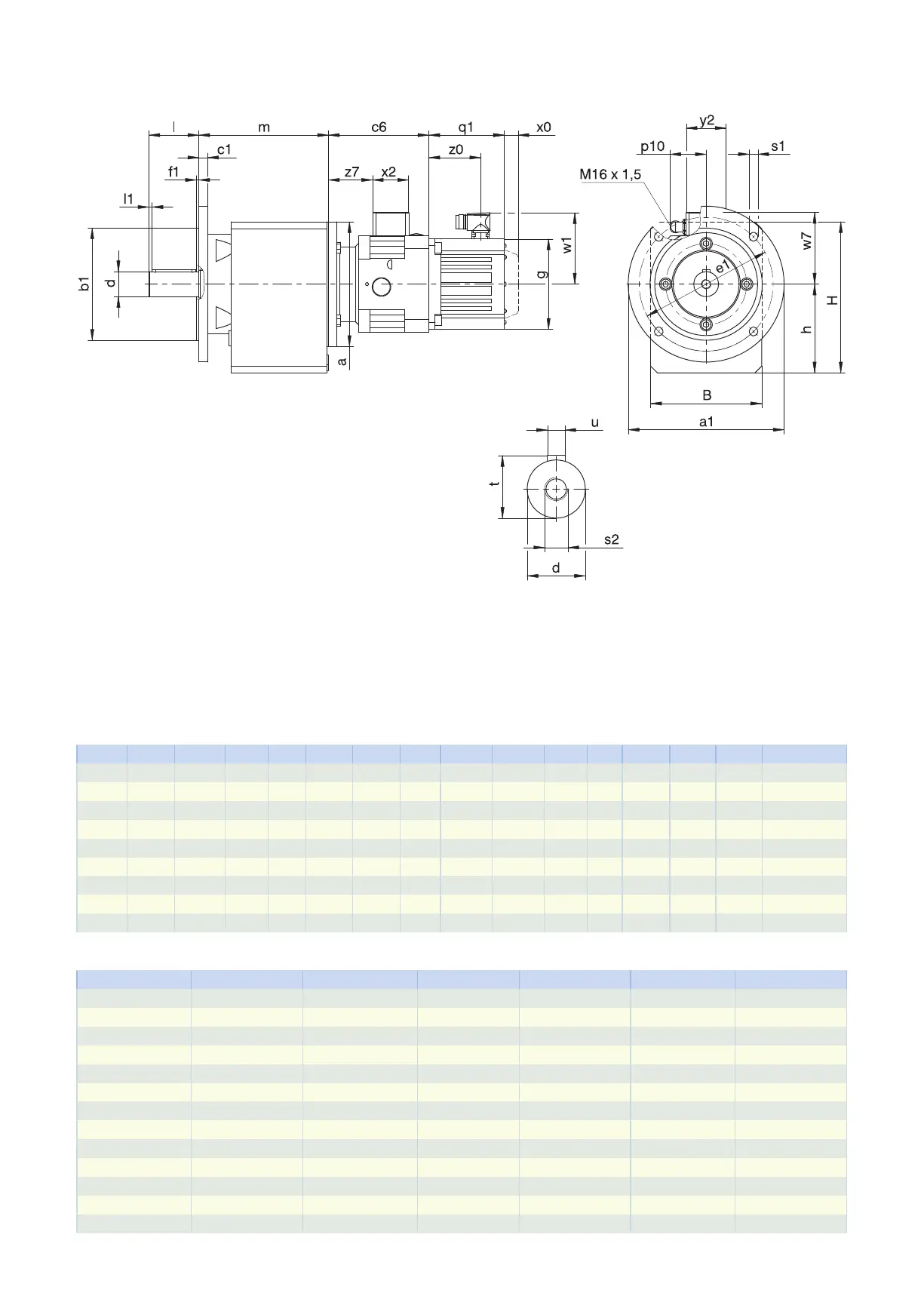
5.3.3 Solid shaft design with feather key, F housing design (round flange)
q1 Applies to motors with brake. x0 Applies to encoders using an optical measuring method.
w1 Different for the One Cable Solution (OCS), see the chap-
ter [}11.4]
C612: Motor adapter and gear unit are sometimes non-coaxial.
Options: C0 − C5 also available with solid shaft without feather key; on request starting at C6.
Dimensions of gear units
Type
∅
a1
∅
b1
B c1
∅
d
∅
e1
f1 h H l l1
∅
s1
s2 t u
C0 160 110
j6
97 10 20
k6
130 3.0 79.0 141.0 40 3 9 M6 22.5 A6×6×32
C1 200 130
j6
130 12 25
k6
165 3.5 100.0 175.0 50 5 11 M10 28.0 A8×7×40
C2 200 130
j6
142 12 30
k6
165 3.5 112.0 192.0 60 5 11 M10 33.0 A8×7×50
C3 250 180
j6
154 12 30
k6
215 4.0 127.0 212.0 60 5 14 M10 33.0 A8×7×50
C4 250 180
j6
178 14 40
k6
215 4.0 142.5 242.5 80 5 14 M16 43.0 A12×8×70
C5 300 230
j6
195 16 40
k6
265 4.0 166.0 286.0 80 5 14 M16 43.0 A12×8×70
C6 300 230
j6
225 17 50
k6
265 4.0 195.0 310.0 100 5 14 M16 53.5 A14×9×90
C7 350 250
h6
265 18 60
m6
300 5.0 231.0 371.0 120 5 18 M20 64.0 A18×11×100
C8 400 300
h6
310 20 70
m6
350 5.0 285.0 445.0 140 5 18 M20 74.5 A20×12×125
Dimensions of additional round flanges
Type
∅
a1
∅
b1
c1
∅
e1
f1
∅
s1
C0 120 80
j6
10 100 3.0 7
C0 140 95
j6
10 115 3.0 9
C1 140 95
j6
8 115 3.5 9
C1 160 110
j6
10 130 3.5 9
C2 160 110
j6
10 130 3.5 9
C2 250 180
j6
12 215 4.0 14
C3 160 110
j6
10 130 3.5 9
C3 200 130
j6
12 165 3.5 11
C4 200 130
j6
14 165 3.5 11
C4 300 230
j6
14 265 4.0 14
C5 250 180
j6
14 215 4.0 14
C8 350 250
h6
18 300 5.0 18
C8 450 350
h6
20 400 5.0 18
5.3 Dimensional drawings 5 Chelical geared motors
116