13.4.4 Connection assignment of the encoder plug connector
The size and connection assignment of the encoder plug connectors depend on the model of encoder in-
stalled and the size of the motor.
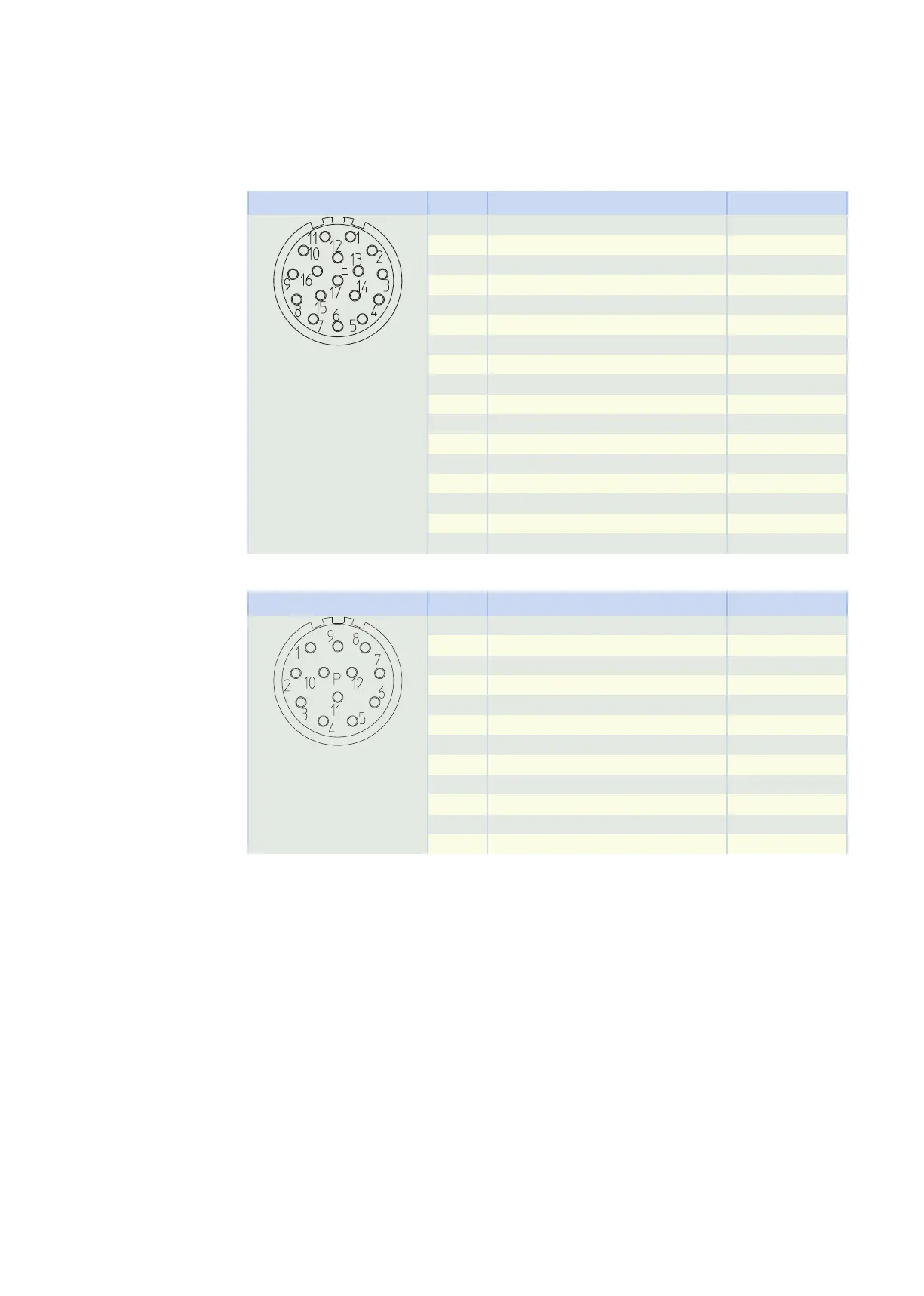
EnDat 2.1 encoder with sin/cos incremental signals, plug connector size con.23
Connection diagram Pin Connection Color
1 B − (Sin −) RDBK
2 0 V GND WHGN
3 A − (Cos −) YEBK
4 Up + BNGN
5 Data + GY
6
7 1TP1 (Temperature sensor +) BK/RD
8 Clock + VT
9 B + (Sin +) BUBK
10 0 V sense WH
11 A + (Cos +) GNBK
12 Up sense BU
13 Data − PK
14 1TP2 (Temperature sensor –) WH/WH
15 Clock − YE
16
17
Resolver, plug connector size con.23
Connection diagram Pin Connection Color
1
2 1TP1 (Temperature sensor +) BK/RD
3 S4 Sin + BU
4 S3 Cos + BK
5 R2 Ref + YEWH
6 1TP2 (Temperature sensor –) WH/WH
7 S2 Sin − YE
8 S1 Cos − RD
9 R1 Ref − RDWH
10
11
12
13.4 Connection to Kollmorgen drive controllers 13 Connecting to drive controllers of third-party manufac-
turers
436