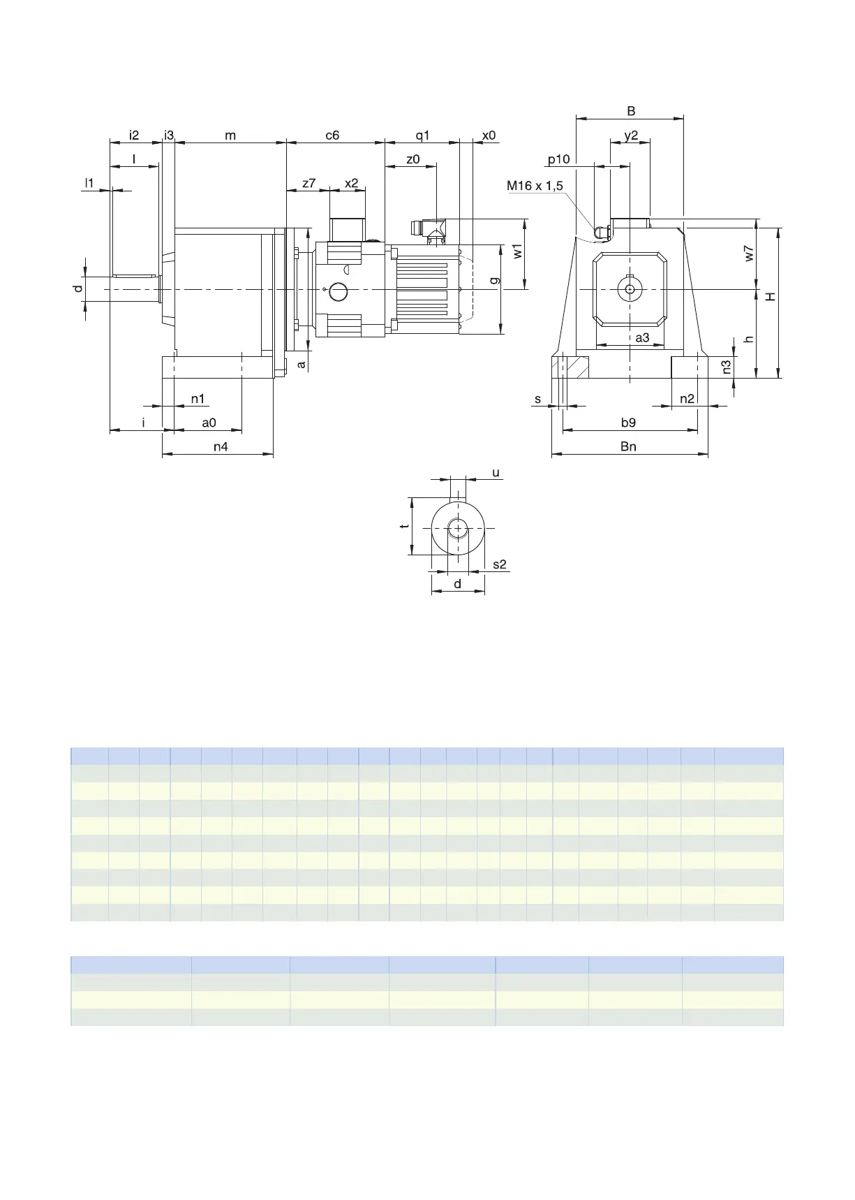
5.3.1 Solid shaft design with feather key, N housing design (foot)
q1 Applies to motors with brake. x0 Applies to encoders using an optical measuring method.
w1 Different for the One Cable Solution (OCS), see the chap-
ter [}11.4]
C612: Motor adapter and gear unit are sometimes non-coaxial.
Options: C0 − C5 also available with solid shaft without feather key; on request starting at C6.
Dimensions of gear units
Type a0 a3 b9 B Bn
∅
d
h H i i2 i3 l l1 n1 n2 n3 n4
∅
s
s2 t u
C0 62 60 110 92 132 20
k6
82 144 55 44 13 40 3 11 35 20 95.0 7 M6 22.5 A6×6×32
C1 70 80 150 124 176 25
k6
102 177 67 54 15 50 5 13 42 25 117.5 9 M10 28.0 A8×7×40
C2 85 95 170 138 200 30
k6
115 195 79 65 21 60 5 14 50 30 134.5 11 M10 33.0 A8×7×50
C3 105 95 185 150 215 30
k6
130 215 79 65 20 60 5 14 50 30 153.5 11 M10 33.0 A8×7×50
C4 110 110 220 175 255 40
k6
145 245 105 86 20 80 5 19 60 35 180.0 14 M16 43.0 A12×8×70
C5 130 130 245 192 290 40
k6
170 290 108 86 21 80 5 22 70 40 197.0 18 M16 43.0 A12×8×70
C6 215 177 245 225 300 50
k6
200 315 130 106 47 100 5 25 75 40 265.0 18 M16 53.5 A14×9×90
C7 235 192 300 265 365 60
m6
235 375 163 127 58 120 5 25 90 50 285.0 18 M20 64.0 A18×11×100
C8 300 223 340 310 435 70
m6
290 450 190 148 70 140 5 29 95 55 360.0 22 M20 74.5 A20×12×125
Motor adapter dimensions
Type c6 p10 w7 x2 y2 z7
C_MB23 140 59 102.9 58 64 57.5
C_MB33 161 59 115.4 58 64 71.0
C_MB43 194 59 134.9 58 64 93.5
5.3 Dimensional drawings 5 Chelical geared motors
112