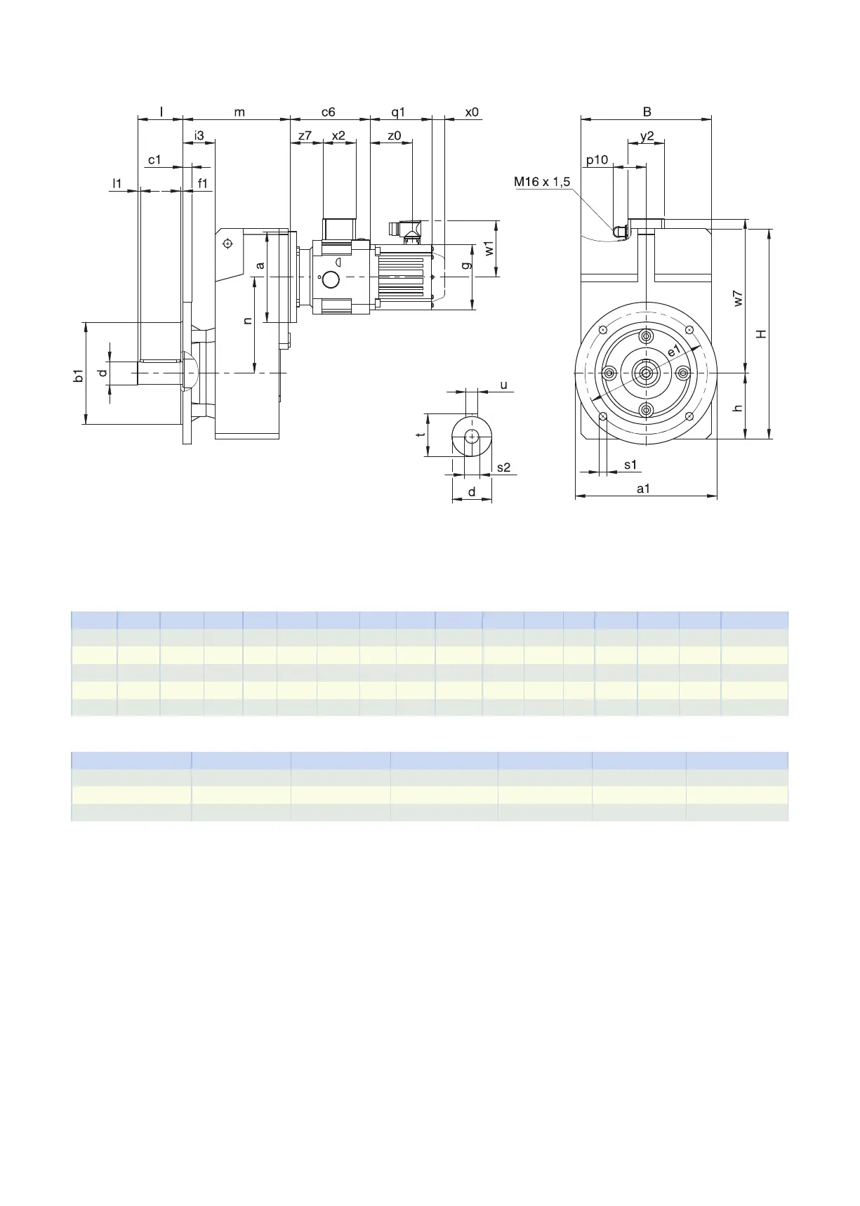
6.3.5 V shaft design (solid shaft), F housing design (round flange)
q1 Applies to motors with brake. x0 Applies to encoders using an optical measuring method.
w1 Different for the One Cable Solution (OCS), see the chap-
ter [}11.4]
Dimensions of gear units
Type
∅
a1
∅
b1
B c1
∅
d
∅
e1
f1 h H i3 l l1
∅
s1
s2 t u
F1 160 110
j6
145 10 25
k6
130 3.5 74 238.0 44.5 50 5 9 M10 28.0 A8×7×40
F2 200 130
j6
180 14 30
k6
165 3.5 93 299.0 53.0 60 5 11 M10 33.0 A8×7×50
F3 250 180
j6
206 15 35
k6
215 4.0 106 335.5 56.5 70 5 14 M12 38.0 A10×8×60
F4 250 180
j6
230 15 40
k6
215 4.0 116 370.0 56.5 80 5 14 M16 43.0 A12×8×70
F6 300 230
j6
265 17 50
k6
265 4.0 137 433.0 60.5 100 5 14 M16 53.5 A14×9×90
Motor adapter dimensions
Type c6 p10 w7 x2 y2 z7
F_MB23 140 59 102.9 58 64 57.5
F_MB33 161 59 115.4 58 64 71.0
F_MB43 194 59 134.9 58 64 93.5
6.3 Dimensional drawings 6 Foffset helical geared motors
156