10.6.2 Permitted shaft loads for the output shaft
The values specified in the tables apply to the permitted shaft loads:
• For shaft dimensions in accordance with the catalog
• For output speeds n
2m*
≤ 20 rpm (F
2axN
= F
2ax20
; F
2radN
= F
2rad20
; M
2kN
= M
2k20
)
• Only if radial forces on the gear unit are stabilized by its pilots for the pitch circle diameter and flange
housing design
10.6.2.1 V shaft design
Permitted shaft loads for V shaft design (solid shaft)
Type z
2
F
2ax20
F
2rad20
F
2rad,acc
M
2k20
M
2k,acc
[mm] [N] [N] [N] [Nm] [Nm]
K1 40.0 1900 5000 5000 325 325
K2 42.0 2100 6000 6000 430 430
K3 45.0 2400 7000 7000 525 525
K4 52.0 3500 11200 11200 1050 1050
K5 72.0 3500 13450 13450 1580 1580
K6 72.0 4000 16000 16000 1960 1960
K7 85.0 5500 22000 22000 3200 3200
K8 60.0 7250 29000 29000 3800 3800
K9 87.0 16500 65000 65000 11200 11200
K10 84.0 25000 80000 80000 15200 15200
Reduced values apply in the case of a V shaft design (solid shaft) in conjunction with an NF housing design
(foot + round flange):
Type z
2
F
2ax20
F
2rad20
F
2rad,acc
M
2k20
M
2k,acc
[mm] [N] [N] [N] [Nm] [Nm]
K10 132.0 25000 64000 64000 15200 15200
For the V solid shaft design on both sides, the values for F
2rad20
and M
2k20
must be multiplied by a factor of
0.7.
For other output speeds, download diagrams at https://configurator.stoeber.de/en-US/
.
The following applies to output speeds n
2m*
> 20 rpm:
2ax 20
2axN
2m*
3
1
F
F
n
20min
-
=
2rad20
2radN
2m*
3
1
F
F
n
20min
-
=
The values for F
2ax20
, F
2rad20
and M
2k20
can be found in the table "Permitted shaft loads" in this chapter.
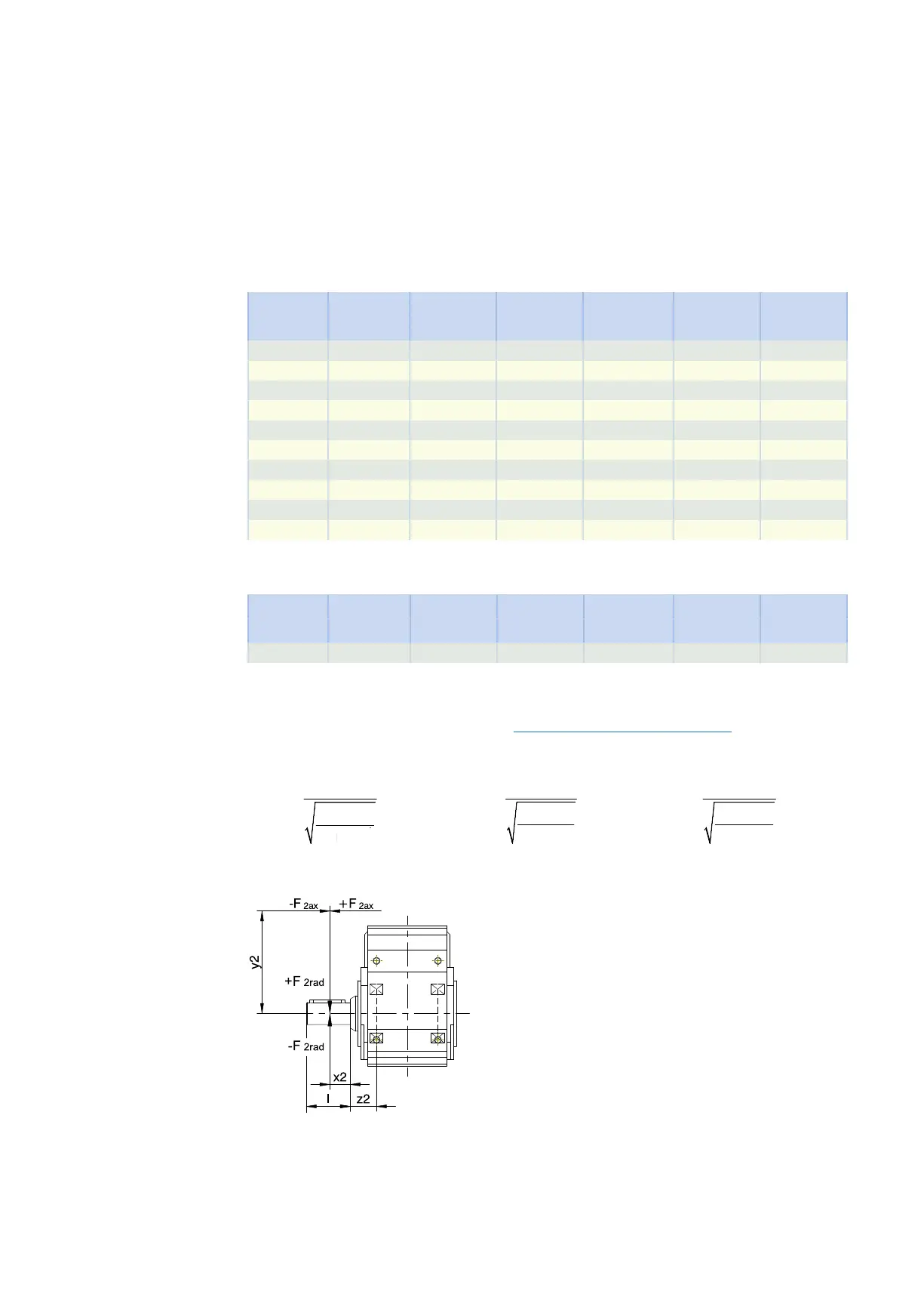
Fig.2: Force application points for solid shaft
The specified values for F
2rad20
and F
2rad,acc
refer to an application of force at the center of the output shaft: x
2
= l/2.
Shaft dimensions can be found in the "Dimensional drawings" chapter.
10.6 Project configuration 10 Khelical bevel geared motors
370