13.6.3 Connection assignment of the power plug connector
The size and connection plan of the power plug connector depend on the size of the motor. The colors of
the connecting wires inside the motor are specified in accordance with IEC 60757.
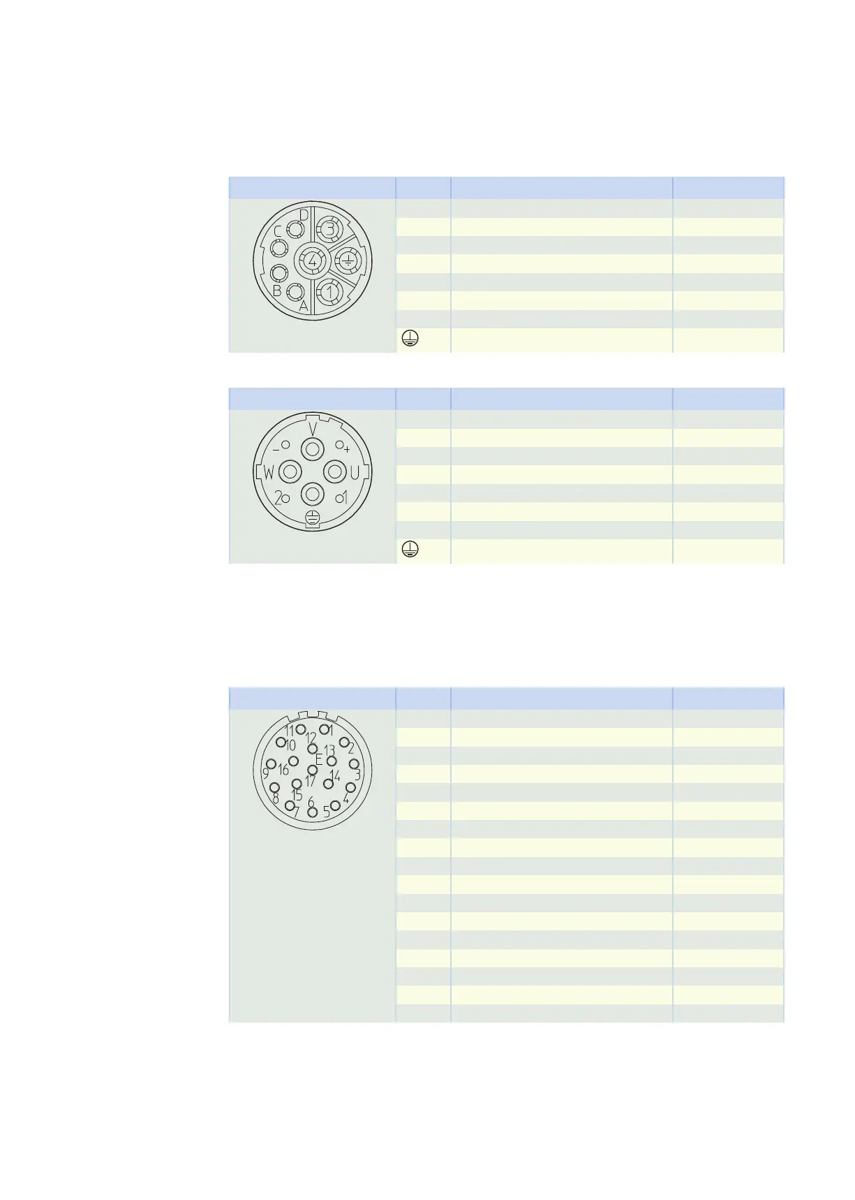
Plug connector size con.23
Connection diagram Pin Connection Color
1 U phase BK
3 W phase RD
4 V phase BU
A Brake + RD
B Brake − BK
C Temperature sensor +
D Temperature sensor −
Grounding conductor GNYE
Plug connector size con.40 (1.5)
Connection diagram Pin Connection Color
U U phase BK
V V phase BU
W W phase RD
+ Brake + RD
− Brake − BK
1 Temperature sensor +
2 Temperature sensor −
Grounding conductor GNYE
13.6.4 Connection assignment of the encoder plug connector
The size and connection assignment of the encoder plug connectors depend on the model of encoder in-
stalled and the size of the motor.
EnDat 2.1 encoder with sin/cos incremental signals, plug connector size con.23
Connection diagram Pin Connection Color
1 B − (Sin −) RDBK
2 0 V GND WHGN
3 A − (Cos −) YEBK
4 Up + BNGN
5 Data + GY
6
7
8 Clock + VT
9 B + (Sin +) BUBK
10 0 V sense WH
11 A + (Cos +) GNBK
12 Up sense BN
13 Data − PK
14
15 Clock − YE
16
17
13 Connecting to drive controllers of third-party manufacturers 13.6 Connection to Beckhoff drive controllers
441