13.5.2 Possible combinations with drive controllers
The following table shows the possible combinations of STOBER synchronous servo motors with drive con-
trollers from Bosch Rexroth depending on the encoder model.
Drive controller IndraDrive C/Cs
Drive controller code FW
DC link voltage U
ZK
540V
Connection plan ID 442445
Encoder Encoder code
EnDat 2.1 ECI 119 C4 EZHD, EZM
EnDat 2.1 EQN 1125 FMA M2 EZ, EZS
EnDat 2.1 EQN 1125 Q4 EZ, EZS
EnDat 2.1 ECN 1113 FMA M0 EZ, EZS
EnDat 2.1 ECN 1113 C6 EZ, EZS
SEK90 H4 EZHD, EZM
The encoder and drive controller codes are a part of the type designation of the motor.
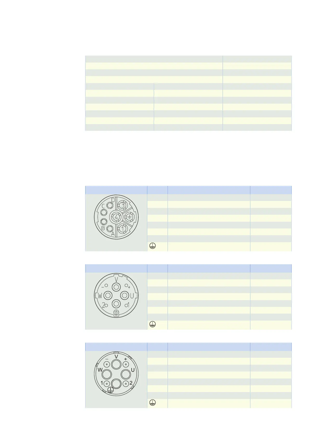
13.5.3 Connection assignment of the power plug connector
The size and connection plan of the power plug connector depend on the size of the motor. The colors of
the connecting wires inside the motor are specified in accordance with IEC 60757.
Plug connector size con.23
Connection diagram Pin Connection Color
1 U phase BK
3 V phase BU
4 W phase RD
A Brake + RD
B Brake − BK
C Temperature sensor +
D Temperature sensor −
Grounding conductor GNYE
Plug connector size con.40 (1.5)
Connection diagram Pin Connection Color
U U phase BK
V V phase BU
W W phase RD
+ Brake + RD
− Brake − BK
1 Temperature sensor +
2 Temperature sensor −
Grounding conductor GNYE
Plug connector size con.58 (3)
Connection diagram Pin Connection Color
U U phase BK
V V phase BU
W W phase RD
+ Brake + RD
− Brake − BK
1 Temperature sensor +
2 Temperature sensor −
Grounding conductor GNYE
13.5 Connection to Bosch Rexroth drive controllers 13 Connecting to drive controllers of third-party manu-
facturers
438