13.2.5 Terminal assignment for plug connectors (One Cable Solution)
In the One Cable Solution design, the power and encoder lines are connected using a shared plug connector.
The temperature sensor of the motor is connected to the encoder internally. The measured values from the
temperature sensor are transmitted via the log of the encoder.
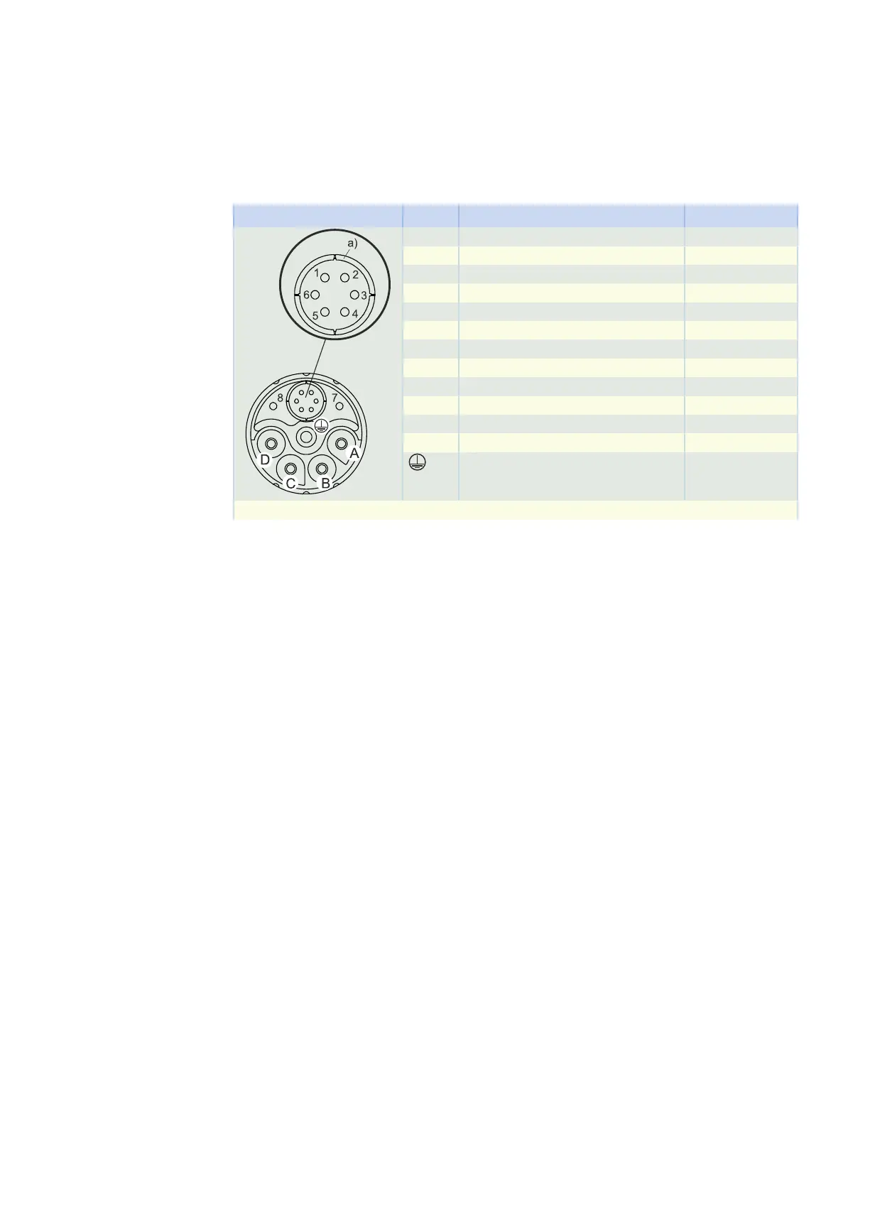
Plug connector size con.23
Connection diagram Pin Connection Color
A U phase black
B V phase blue
C W phase red
D
1 Up + browngreen
2 0 V GND whitegreen
3 Data + grey
4 Data − pink
5 Clock + violet
6 Clock − yellow
7 Brake −
8 Brake +
Grounding conductor green-yellow
a) Coaxial shield to which the shield of the encoder cores is connected
13.2 Connection to B&R drive controllers 13 Connecting to drive controllers of third-party manufacturers
428