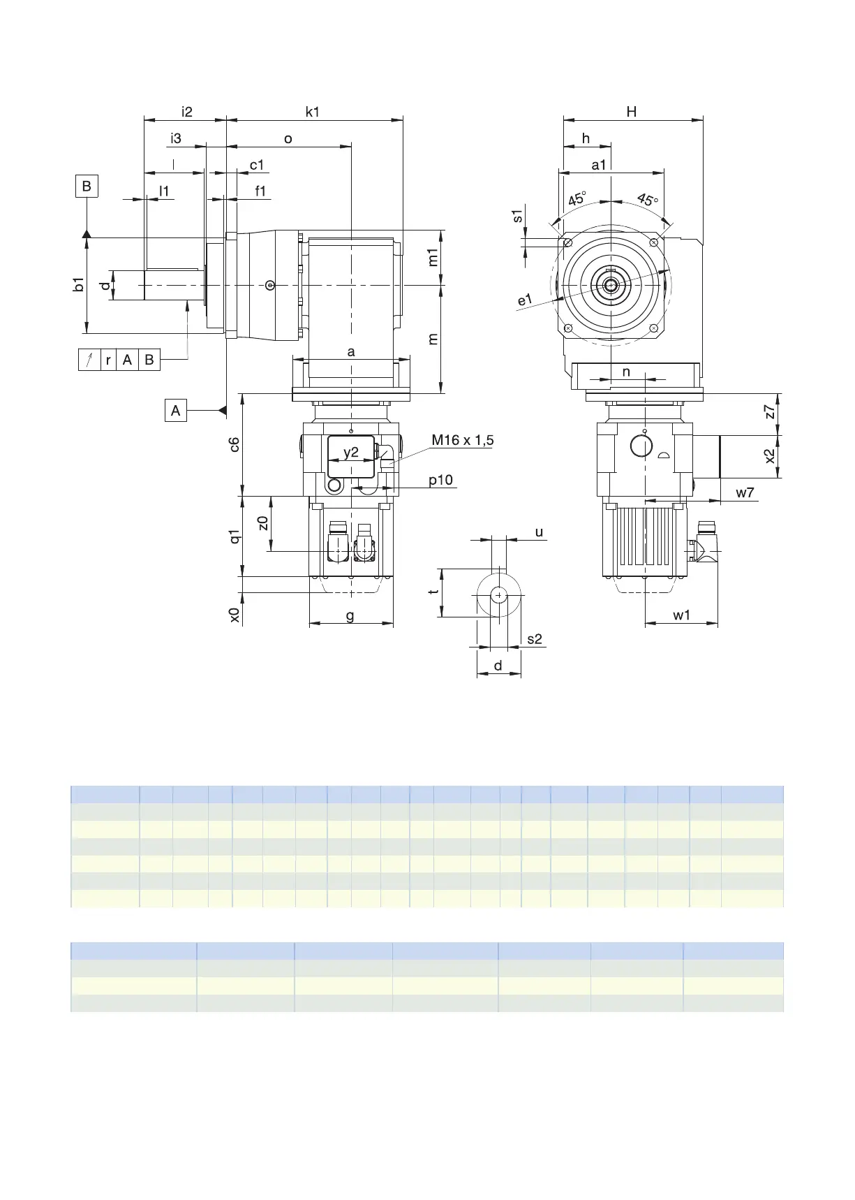
7.3.1 P shaft design (solid shaft with feather key)
q1 Applies to motors with brake. x0 Applies to encoders using an optical measuring method.
w1 Different for the One Cable Solution (OCS), see the chap-
ter [}11.4]
− The radial runout specification applies only to the rein-
forced bearingD.
Dimensions of gear units
Type
☐
a1
∅
b1
c1
∅
d
∅
e1
f1 h H i2 i3 k1 l l1 m1 o r
∅
s1
s2 t u
P531_K102_ 101 90
h6
10 32
k6
120 15.0 60 160 88 28 199.5 58 3 60 143.5 0.030 9.0 M12 35.0 A10×8×50
P731_K102_ 144 130
h6
15 40
k6
165 3.5 60 160 112 27 212.5 82 4 72 156.5 0.035 11.0 M16 43.0 A12×8×70
P731_K202_ 144 130
h6
15 40
k6
165 3.5 65 190 112 27 240.5 82 4 72 170.5 0.035 11.0 M16 43.0 A12×8×70
P831_K202_ 190 160
h6
15 55
k6
215 10.0 65 190 112 27 277.5 82 6 95 207.5 0.035 13.5 M20 59.0 A16×10×70
P831_K302_ 190 160
h6
15 55
k6
215 10.0 75 213 112 27 291.0 82 6 95 215.0 0.035 13.5 M20 59.0 A16×10×70
P931_K402_ 212 180
h6
17 75
k6
250 10.0 90 240 143 34 350.5 105 7 115 260.5 0.040 17.5 M20 79.5 A20×12×90
Motor adapter dimensions
Type c6 p10 w7 x2 y2 z7
PK_MB23 140 59 102.9 58 64 57.5
PK_MB33 161 59 115.4 58 64 71.0
PK_MB43 194 59 134.9 58 64 93.5
7.3 Dimensional drawings 7 PKright-angle planetary geared motors
202