Encoder plug connector features
Motor type Size Connection Turning range
α β
EZ2 – EZ7, EZ802, EZ803, EZ805U, EZHD,
EZM, EZS
con.23
2
Quick lock 180° 20°
EZ805B con.23
3
Quick lock 180° 0°
Notes
• In turning range β, the power or encoder plug connectors can be turned only if doing so does not cause
them to collide.
• The number after "con." indicates the approximate external thread diameter of the plug connector in
mm (for example, con.23 designates a plug connector with an external thread diameter of about 23
mm).
13.1.3 Connection cables
The plug connectors and connection assignment of STOBER synchronous servo motors are designed for con-
necting to drive controllers from third-party manufacturers in such a way that allows you to connect the
original cable of the respective manufacturer. Keep the following information regarding cable quality and
design in mind.
• Because the original cable from Bosch Rexroth cannot be used, STOBER offers suitable cables for this
purpose. More detailed information is available from your STOBER customer consultant.
• Ensure that the cable quality and cable design is suitable for the ambient conditions at the installation
location.
Electromagnetic compatibility (EMC)
Ensure compliance with statutory EMC requirements for the drive system at the installation location.
Connect the cable shields on both ends of the connection cable. Connect the grounding screw of the syn-
chronous servo motor with the grounding at the installation location.
Power cables
Operation with unsuitable power cables may lead to inadmissibly high voltage peaks, which could damage
the motor. For this reason, the capacitances and inductances must match the motor. Recommended values
can be found in the table below.
The conductor cross-section of the power cable must be designed appropriately for the stall current of the
motor. Details on this can be found in the table below.
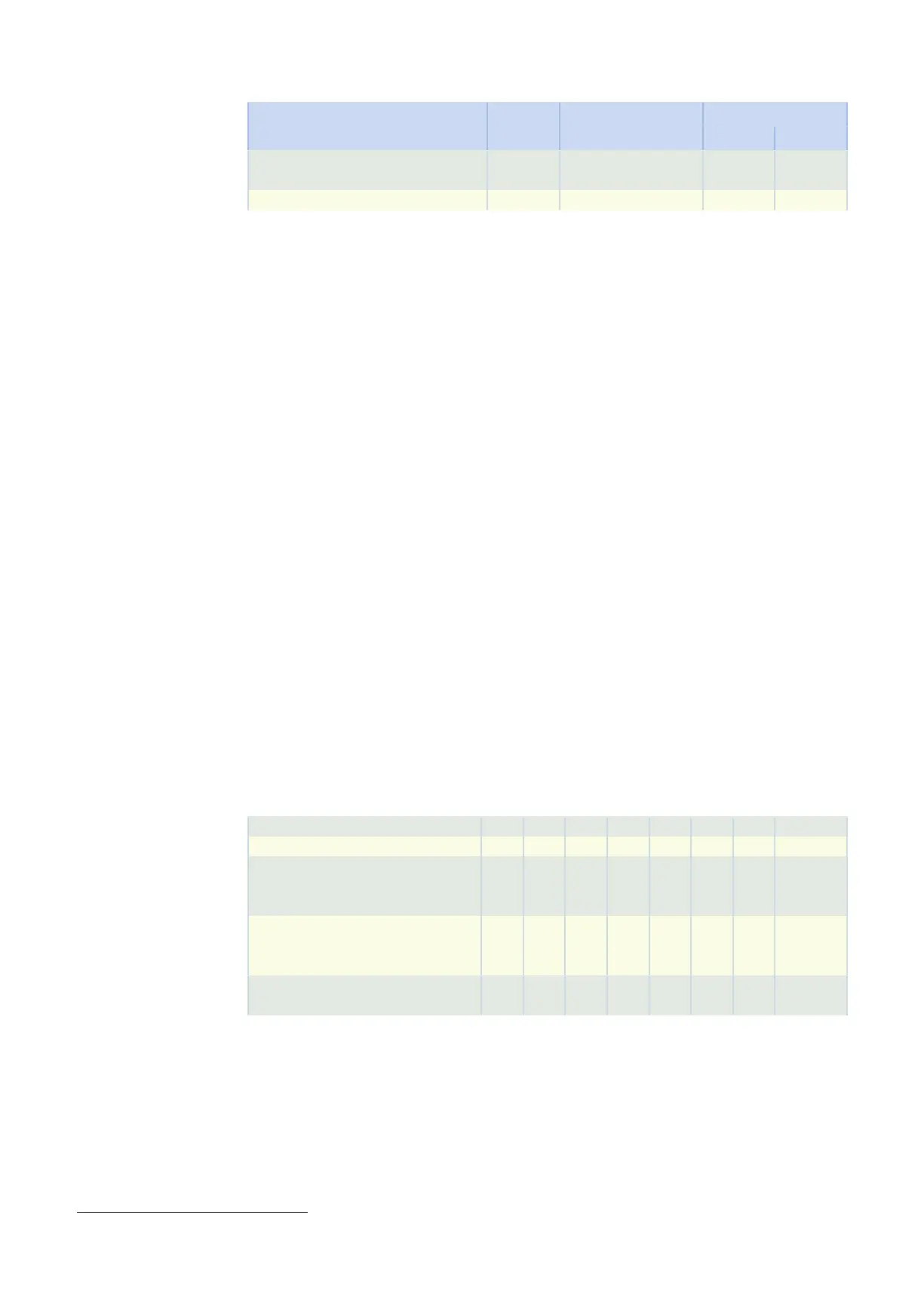
Conductor cross-section [mm²] 1.0 1.5 2.5 4.0 6.0 10.0 16.0 25.0
Nominal current [A] 12.5 15.0 20.0 28.3 35.8 49.2 66.7 90.0
Maximum capacitance in accordance
with
test type A (core/core) [nF/km]
45 55 65 60 70 75 75 Values on
request
Maximum capacitance in accordance
with
test type B (core/residual) [nF/km]
250 300 325 260 300 350 360 Values on
request
Maximum inductance (core/core) [µH/
km]
800 700 700 600 650 600 570 Values on
request
Notes
• The maximum capacitance is specified in accordance with DIN VDE 0472-504. Specifications in accor-
dance with EN 50289-1-5 in preparation.
• The maximum inductance is specified in accordance with EN 50289-1-12.
2
con.15 for connection to B&RACOPOSmulti with EnDat2.2 Interface (drive controller type code GG).
3
con.15 for connection to B&RACOPOSmulti with EnDat2.2 Interface (drive controller type code GG).
13.1 General notes 13 Connecting to drive controllers of third-party manufacturers
422