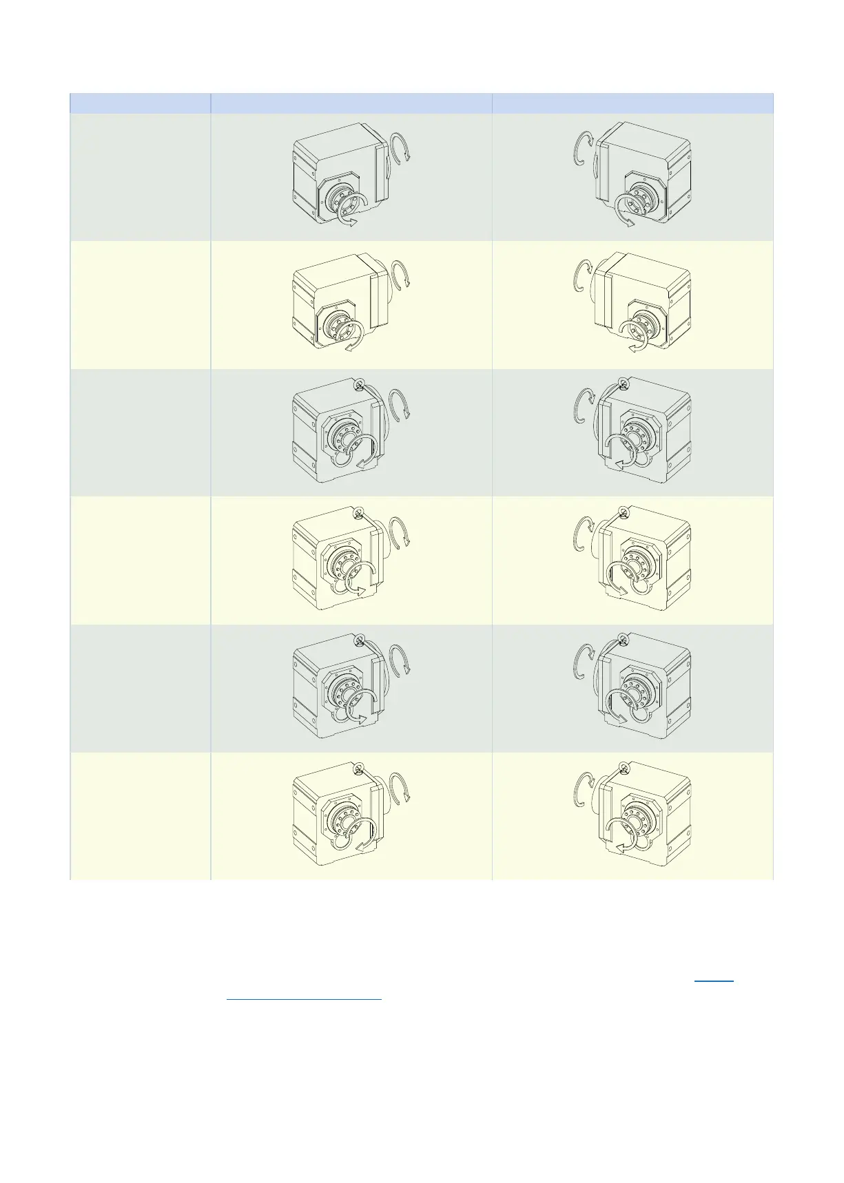
Hollow shaft with shrink ring (S)
Type Shrink ring side 4 Shrink ring side 3
K102 − K402
K203 − K403
K513 − K813
K514 − K814
K913 − K1013
K914 − K1014
The pictures show mounting position EL1.
10.6 Project configuration
Project your drives using our SERVOsoft designing software. Download SERVOsoft for free at https://
www.stoeber.de/en/ServoSoft.
It is the most convenient and reliable method of drive selection, as the entire torque/speed curve of the ap-
plication is displayed and evaluated here in the curve of the geared motor.
In this chapter, only limit values for specific operating points can be taken into consideration for manual
drive selection.
An explanation of the formula symbols can be found in Chapter Symbols in formulas.
The formula symbols for values actually present in the application are marked with *.
10.6 Project configuration 10 Khelical bevel geared motors
364