13.7.5 Terminal assignment for plug connectors (One Cable Solution)
In the One Cable Solution design, the power and encoder lines are connected using a shared plug connector.
The size of the plug connector depends on the size of the motor.
The temperature sensor of the motor is connected to the encoder internally. The measured values from the
temperature sensor are transmitted via the log of the encoder.
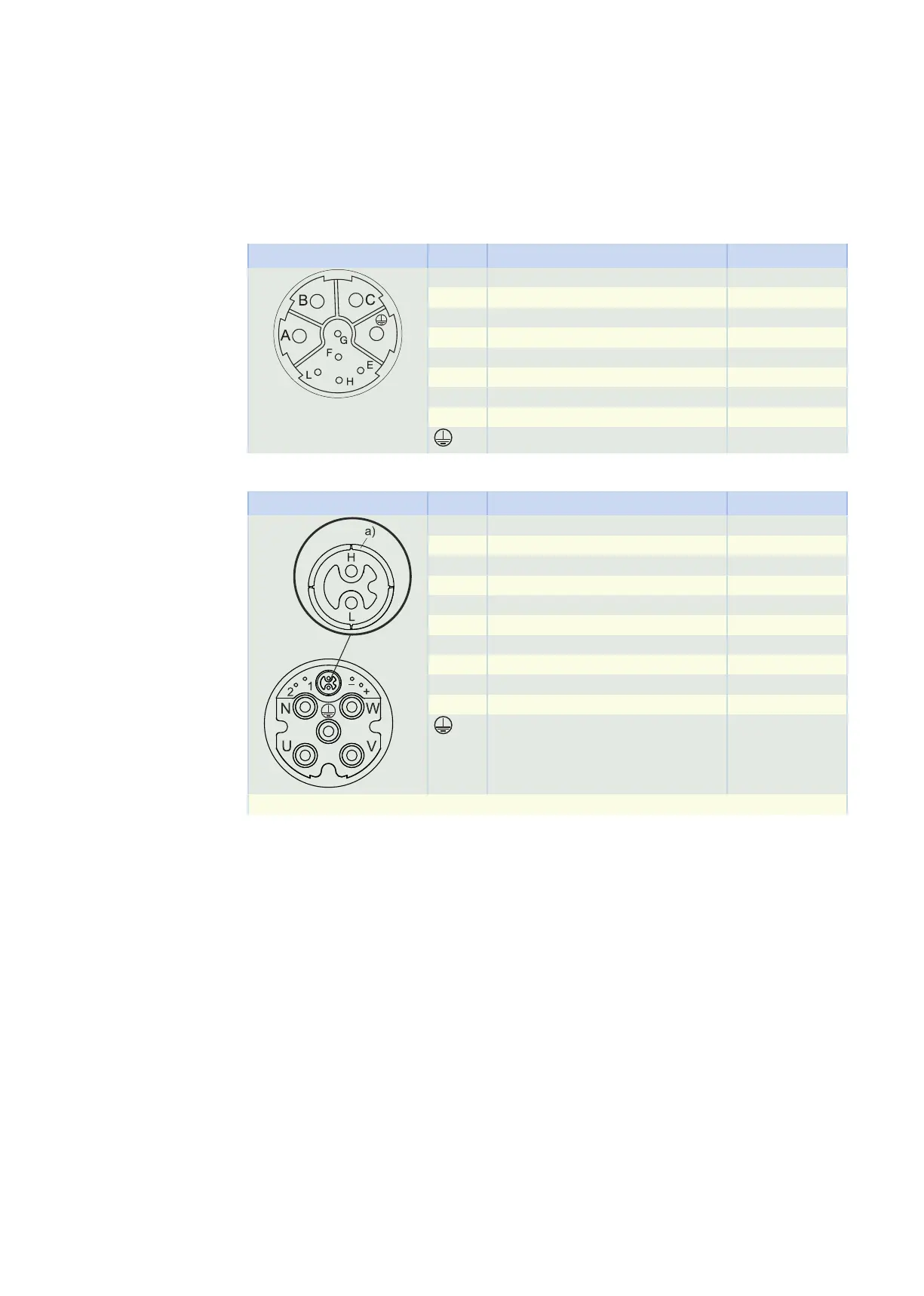
Plug connector size con.23
Connection diagram Pin Connection Color
A 1U1 (U phase) BK
B 1V1 (V phase) BU
C 1W1 (W phase) RD
E DATA + (DSL +) GY
F MBRK + (1BD1) RD
G MBRK − (1BD2) BK
H DATA – (DSL –) GN
L
PE (grounding conductor) GNYE
Plug connector size con.40 (1.5)
Connection diagram Pin Connection Color
U 1U1 (U phase) BK
V 1V1 (V phase) BU
W 1W1 (W phase) RD
N
+
−
1 MBRK + (1BD1) RD
2 MBRK − (1BD2) BK
H DATA – (DSL –) GY
L DATA + (DSL +) GN
PE (grounding conductor) GNYE
a) Coaxial shield to which the DSL shield is connected
13.7 Connection to Allen-Bradley drive controllers 13 Connecting to drive controllers of third-party manufac-
turers
444