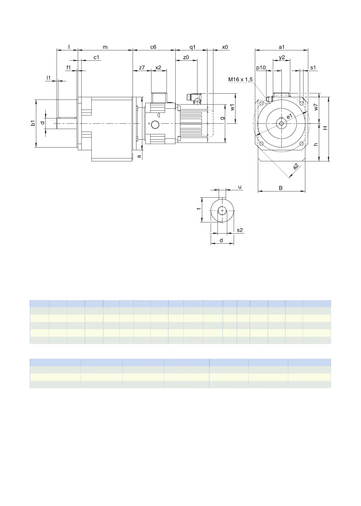
5.3.4 Solid shaft design with feather key, Q housing design (square flange)
q1 Applies to motors with brake. x0 Applies to encoders using an optical measuring method.
w1 Different for the One Cable Solution (OCS), see the chap-
ter [}11.4]
Options: C0 − C4 also available with solid shaft without feather key.
Dimensions of gear units
Type
☐
a1
☐
a2
∅
b1
B c1
∅
d
∅
e1
f1 h H l l1
∅
s1
s2 t u
C0 124 160 110
j6
97 9 20
k6
130 3.0 79.0 141.0 40 3 9 M6 22.5 A6×6×32
C1 145 192 130
j6
130 11 25
k6
165 3.5 100.0 175.0 50 5 11 M10 28.0 A8×7×40
C2 145 192 130
j6
142 11 30
k6
165 3.5 112.0 192.0 60 5 11 M10 33.0 A8×7×50
C3 200 250 180
j6
154 14 30
k6
215 4.0 127.0 212.0 60 5 14 M10 33.0 A8×7×50
C4 200 250 180
j6
178 14 40
k6
215 4.0 142.5 242.5 80 5 14 M16 43.0 A12×8×70
Motor adapter dimensions
Type c6 p10 w7 x2 y2 z7
C_MB23 140 59 102.9 58 64 57.5
C_MB33 161 59 115.4 58 64 71.0
C_MB43 194 59 134.9 58 64 93.5
5.3 Dimensional drawings 5 Chelical geared motors
118