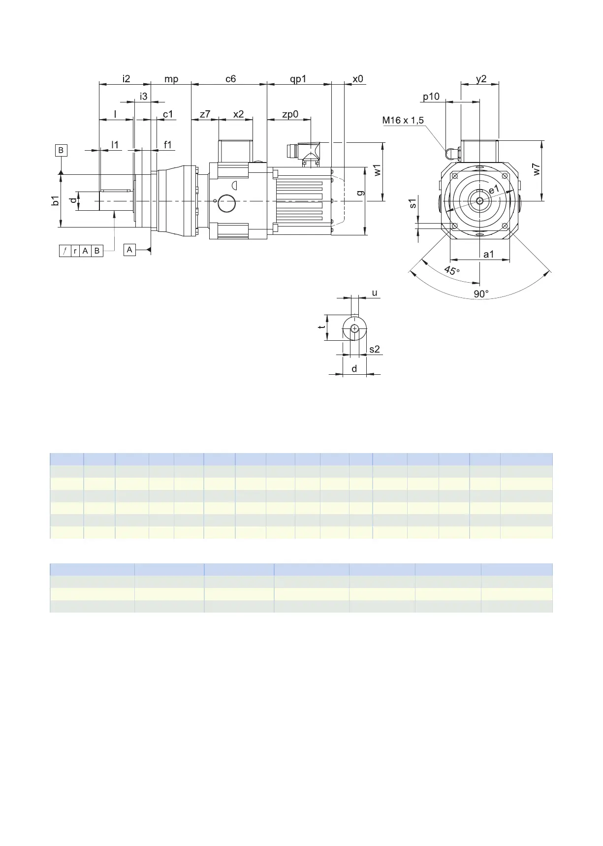
2.3.2 P shaft design (solid shaft with feather key)
qp1 Applies to motors with brake. x0 Applies to encoders using an optical measuring method.
w1 Different for the One Cable Solution (OCS), see the chap-
ter [}11.4]
− The radial runout specification applies only to the rein-
forced bearingD.
Dimensions of gear units
Type
☐
a1
∅
b1
c1
∅
d
∅
e1
f1 i2 i3 l l1 r
∅
s1
s2 t u
P531 101 90
h6
10 32
k6
120 15.0 88 28 58 3 0.030 9.0 M12 35.0 A10×8×50
P731 144 130
h6
15 40
k6
165 3.5 112 27 82 4 0.035 11.0 M16 43.0 A12×8×70
P732 144 130
h6
15 40
k6
165 3.5 112 27 82 4 0.035 11.0 M16 43.0 A12×8×70
P831 190 160
h6
15 55
k6
215 10.0 112 27 82 6 0.035 13.5 M20 59.0 A16×10×70
P832 190 160
h6
15 55
k6
215 10.0 112 27 82 6 0.035 13.5 M20 59.0 A16×10×70
P932 212 180
h6
17 75
k6
250 10.0 143 34 105 7 0.040 17.5 M20 79.5 A20×12×90
Motor adapter dimensions
Type c6 p10 w7 x2 y2 z7
P_MB23 129 59 102.9 58 64 46.5
P_MB33 147 59 115.4 58 64 57.0
P_MB43 176 59 134.9 58 64 75.5
2.3 Dimensional drawings 2 Pplanetary geared motors
24