Permitted shaft loads for radially reinforced bearing Z
Type z
2
F
2ax100
F
2rad100
F
2rad,acc
M
2k100
M
2k,acc
[mm] [N] [N] [N] [Nm] [Nm]
P3 17.5 600 3000 3000 95 95
P4 18.5 1000 5000 5000 183 183
P5 19.5 1600 8000 8000 388 388
P7 23.0 2000 10000 10000 640 640
P8 24.5 3600 18000 18000 1179 1179
P9 33.0 5000 27000 35000 2309 2993
Fig.4: Recommendation for bearing assignment Z (e.g. for belt drives)
For other output speeds, download diagrams at https://configurator.stoeber.de/en-US/
.
The following applies to output speeds n
2m*
> 100 rpm:
2ax100
2axN
2m*
3
1
F
F
n
100min
-
=
2rad100
2radN
2m*
3
1
F
F
n
100min
-
=
The values for F
2ax100
, F
2rad100
and M
2k100
can be found in the table "Permitted shaft loads" in this chapter.
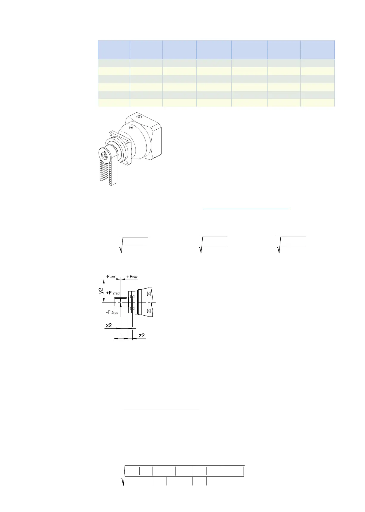
Fig.5: Force application points
The specified values for F
2rad100
and F
2rad,acc
refer to an application of force at the center of the output shaft: x
2
= l/2.
Shaft dimensions can be found in the "Dimensional drawings" chapter.
The following applies to other force application points:
( )
× × + × +
=
2ax * 2 2rad,acc* 2 2
2k,acc*
2 F y F x z
M
1000
For applications with multiple axial and/or radial forces, you must add the forces as vectors.
In the event of EMERGENCY OFF operation (max. 1000 load changes), you can multiply the permitted forces
and torques for F
2ax100
, F
2rad100
and M
2k100
by a factor of two.
Also note the calculation for equivalent values:
× × + + × ×
=
× + + ×
3 3
2m,1* 1* 2k,acc,1* 2m,n* n* 2k,acc,n*
3
2k,eq*
2m,1* 1* 2m,n* n*
n t M ... n t M
M
n t ... n t
2 Pplanetary geared motors 2.6 Project configuration
37