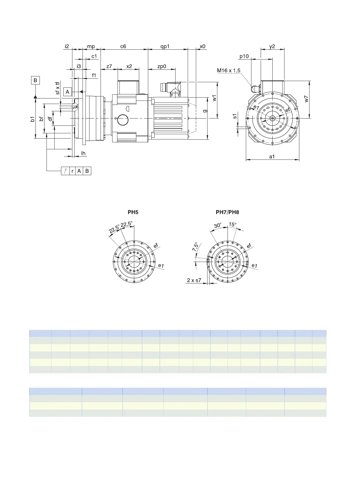
3.3.1 F shaft design (flange shaft)
qp1 Applies to motors with brake. x0 Applies to encoders using an optical measuring method.
w1 Different for the One Cable Solution (OCS), see the chap-
ter [}11.4]
Dimensions of gear units
Type
∅
a1
∅
b1
∅
bf
c1
∅
df
∅
e1
∅
ef
f1 i2 i3 lh r
∅
s1
s7 sf tf
PH531 145
h7
110
h7
80
h7
8 40.0
H6
135 63.0 12 29.0 23.0 6 0.020 5.5 – M6 11
PH731 179
h7
140
h7
100
h7
10 50.0
H6
168 80.0 12 38.0 32.0 6 0.025 6.6 – M8 14
PH732 179
h7
140
h7
100
h7
10 50.0
H6
168 80.0 12 38.0 32.0 6 0.025 6.6 – M8 14
PH831 247
h7
200
h7
160
h7
12 80.0
H6
233 125.0 15 50.0 42.0 8 0.030 9.0 M10 M10 18
PH832 247
h7
200
h7
160
h7
12 80.0
H6
233 125.0 15 50.0 42.0 8 0.030 9.0 M10 M10 18
Motor adapter dimensions
Type c6 p10 w7 x2 y2 z7
PH_MB23 129 59 102.9 58 64 46.5
PH_MB33 147 59 115.4 58 64 57.0
PH_MB43 176 59 134.9 58 64 75.5
3.3 Dimensional drawings 3 PHplanetary geared motors
48