Description Of Specific Functions 111
V560 Series High Performance Closed-Loop Vector Inverter User Manual
2: REV locking
The motor will run in REV direction no matter the FWD running command or REV running command is given.
F0.1.20 Maximum output
frequency
Setting range: 10.00~320.00Hz Factory default: 60.00
F0.1.21 Upper limit frequency
Setting range: [F0.1.22]~Min
(300.00Hz,[F0.1.20])
Factory default: 50.00
F0.1.22 Lower limit frequency Setting range: 0.0Hz~[F0.1.21] Factory default: 0.0
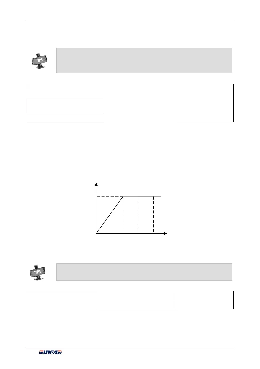
The maximum output frequency is the allowable output maximum frequency of the inverter as set by users
(maximum stator synchronous frequency of the asynchronous motor); The upper limiting frequency is the
maximum frequency allowed for running of the asynchronous motor as set by users (the maximum frequency
corresponding to the mechanical rotor of the asynchronous motor). The maximum output frequency must be
higher than the upper limiting frequency; The lower limiting frequency is the minimum frequency allowed for
running of the motor as set by users.
The maximum output frequency, upper limiting frequency and lower limiting frequency shall carefully set
according to the actual nameplate parameters and operating status of the controlled motor and. The
relationship among the three kinds of frequency is shown in Figure 7-10.
F0.1.23 FWD jog frequency Setting range: 0.0Hz~[F0.1.21] Factory default: 10.00
F0.1.24 REV jog frequency Setting range: 0.0Hz~[F0.1.21] Factory default: 10.00
Jog running is a special running mode of the inverter. No matter the inverter is initially stopped or running, as
long as the jog command is inputted, the inverter will transit to the jog frequency according to the preset jog
acceleration and deceleration time. However, it is also influenced by the startup frequency and startup
frequency duration as well as the functions of DC band-type braking, startup delay and startup pre-excitation.
¾ The function of “Direction locking” (__x_) has precedence over the function of “Direction
switching” (_ _ _X).
¾ It can be set when the inverter is running. Be sure that the operation is safe.
¾ [F1.2.15] in Figure 7-10 represents the motor’s reference frequency, and [F1.2.16]
represents the motor’s reference voltage.
Output
frequency
[F1.2.16]
[F0.1.20][F0.1.22] [F0.1.21][F1.2.15]
Output voltage
Figure 7-10 Frequency parameter definition sketch
 Loading...
