Wiring Of Frequency Inverter 27
V260 Series High Performance Closed-Loop Vector Inverter User Manual
Type
Label of
terminal
Name Function description of terminal Specification
input
AI2—GND Analog input AI2
and other functions with function
code in F4 Group.
0-10V, Input
impendance: 100K
Input current:
0-20mA
Analog
output
AO1—GND
Multifunctional
analog output AO1
The programmable voltage/current
signal output terminal has 45 kinds
of monitoring status to be selected
by programming.
See Reference Table for Monitor
Variables for detail. JP1 and JP2
(see DIP Switch Jumper Selection in
4.3.6 for detail) are selected
current/voltage output
Current output:
0-20mA
Capacity 40Mw,
Input current
impedance:
0~300Ω
Voltage output:
0-10V
AO2—GND
Multifunctional
analog output AO2
Power
supply
GND
Common terminal of
analog signal
VS—GND
+10V/5V power
supply
Supply +10V/10mA or +5V/50mA
power outward
Selection of JP3
(see DIP Switch
Jumper Selection in
4.3.6 for detail)
4.3.3 CAUTIONS TO THE WIRING OF CONTROL TERMINAL
Please pay attention to separate the wiring of control wire and major loop. See section 1.2 for detail.
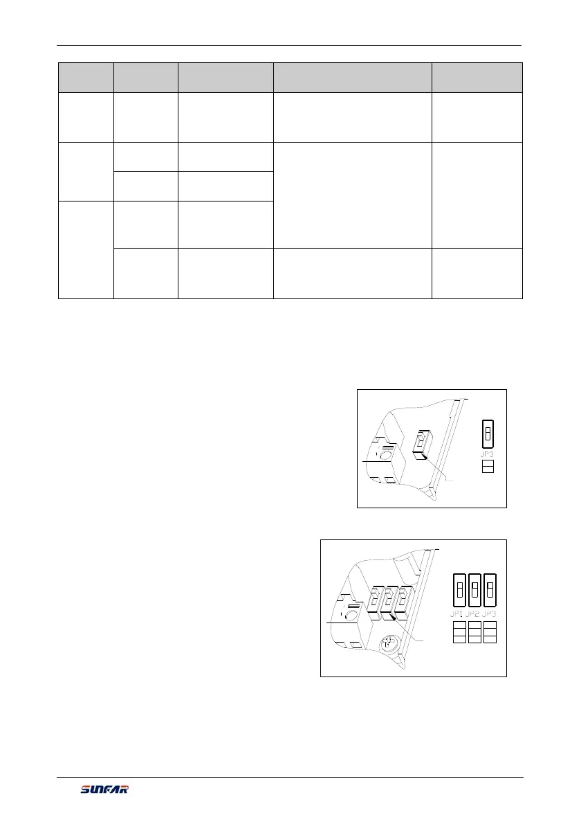
4.3.4 DESCRIPTION OF DIP SWITCH ON CONTROL PANEL
1. One DIP switch have 2 grades
suitable model: inverter model below
V260-4T0022G/4T0030P
1) JP3
V grade : Export
0-10V voltage signal from the AO terminal
A
grade: Provide 0-20mA current signal from AO terminal
2. Three DIP switches have 3 grades
suitable model: inverter model above
V260-4T0030G/4T0040P
1) JP1
VO1 grade: AO1 terminal output voltage signal
OFF grade: AO1 terminal is in suspended status
CO1 grade: AO1 terminal output current signal
2) JP2
VO2 grade: AO2 terminal output voltage signal
OFF grade: AO2 terminal is in suspended status
CO1 grade: AO2 terminal output current signal
3) JP3
5V grade: VS terminal provides 5V voltage signal outward
OFF grade: VS terminal is in suspended status
10V grade: VS terminal provides 10V voltage signal outward
VO1
OFF
CO1
CO2
OFF
VO2 5V
OFF
10V
DIP Switch
V
A
DIP Switch