Wiring Of Frequency Inverter
V260 Series High Performance Closed-Loop Vector Inverter User Manual
32
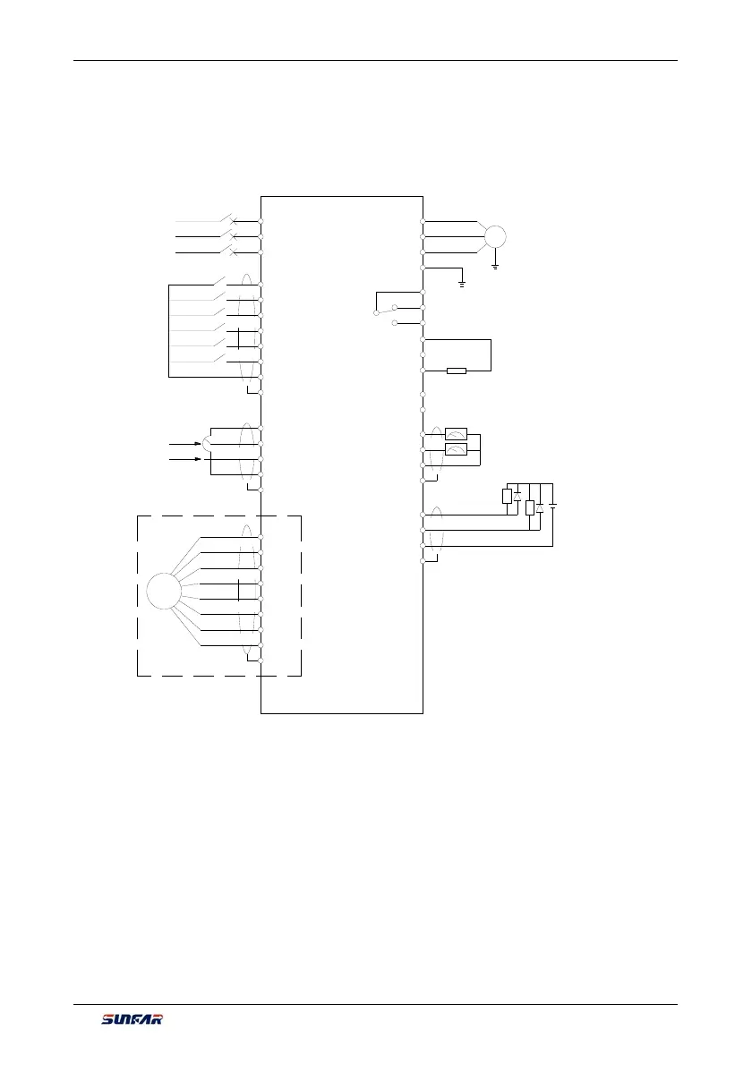
4.5 WIRING CONNECTION OF BASIC OPERATION
Applicable type: V260-4T0007G/4T0011P ~ V260-4T6300G/4T7000P
(Built in brake unit in the inverter below
V260-4T0220G/4T0300P)
E
+12V
GD
A+
A-
B+
B-
Z+
Z-
PG
Open collector
output
E
DO1
DO2
CM
Volt gauge (0-10V)/ammeter (0-20mA)
Volt gauge (0
-10V)/ammeter (0-20mA)
GND
AO2
AO1
E
Auxiliary power
supply
CM
24V
Connected to
braking resistor
P-
P+
PB
Programmable
output
TC
TA
TB
Grounding
E
Motor
M
U
V
W
0-20mA frequency
0
-10V frequency
VS
AI1
AI2
GND
E
T
S
E
CM
DI6
DI5
DI4
DI3
DI2
DI1
R
PG expansion card (optional)
Three-phase breaker
Three-phase power
V260
Figure 4-3 Basic wiring diagram for V260 series frequency inverter