Description Of Specific Functions 153
V560 Series High Performance Closed-Loop Vector Inverter User Manual
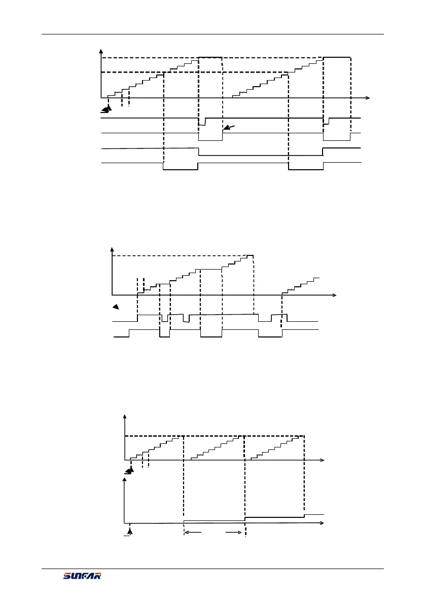
7.22.2 TRIGGER AND GATE CONTROL FUNCTION SETTING OF TIMER
[F5.1.09]
Trigger signal
Clock
Gating signal
7.22.3 CLOCK CONCATENATION FUNCTION SETTING OF TIMER
[F5.1.09]
Trigger signal
Clock
Clock
Trigger signal
UT1
UT2
Figure 7-41-B Schematic diagram of comparison
value of timer 1 reaching for the basic function (F5.1.06=10#1)
Figure 7-41-C Starting trigger and gate control signal function of timer 1 (UT1)
(F5.1.06=1111; F5.1.15=0001)
Figure 7-41-D Pulse concatenation function of timer 1(UT1) (F5.1.06=10#1; F5.1.07=###3)
[F5.1.09]
[F5.1.10]
Cycle reaching (0.5spulse)
Trigger signal
Cycle reaching (level)
Clock
REV after reaching the cycle
REV after reaching the comparative valueor cycle
Reset