Functional Parameter Table
V560 Series High Performance Closed-Loop Vector Inverter User Manual
75
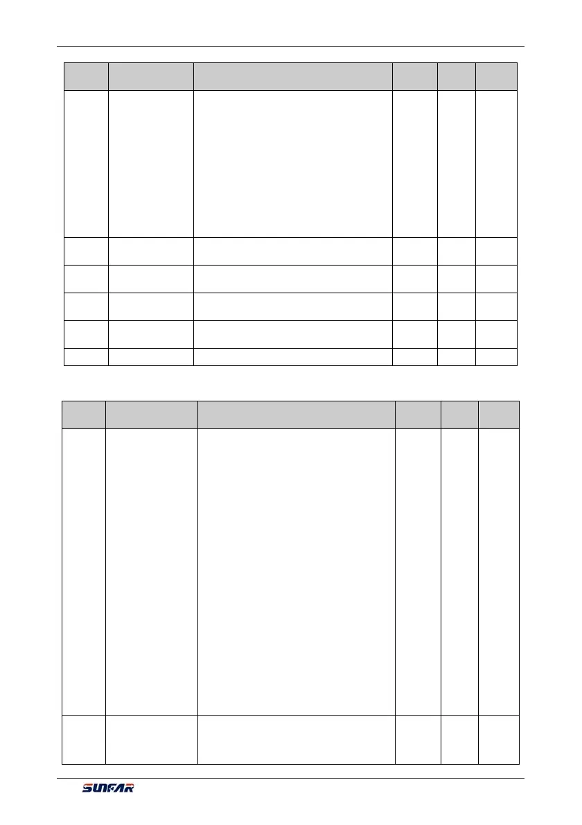
Function
Code
Name Setting Range and Description
Minimum
Unit
Factory
Default
Change
Limit
6: MODBUS Fieldbus set value 2
_ _ X _: Reserved
_ X _ _: Maximum torque selection source
0: Maximum torque set value 1 (F8.3.50)
1: Maximum torque set value 2 (F8.3.51)
2: Multifunctional selection terminal setting 1 or
2 (Function No. 36)
3: AI1 set value
4: AI2 set value
5: MODBUS Fieldbus set value 1
6: MODBUS Fieldbus set value 2
F8.3.48
Minimum torque
limit 1
-250.0~0.0% 0.1 -200.0
F8.3.49
Minimum torque
limit 2
-250.0~0.0% 0.1 -200.0
F8.3.50
Maximum torque
limit 1
0.0~250.0% 0.1 200.0
F8.3.51
Maximum torque
limit 2
0.0~250.0% 0.1 200.0
F8.3.52 Torque zero offset -25.0~25.0% 0.1 0.0
6.2.38 COMPENSATION PID (RUNNING CYCLE: 1MS)
Function
Code
Name Setting Range and Description
Minimum
Unit
Factory
Default
Change
Limit
F9.0.00
Compensation PID
function
_ _ _ X: Controller input
0: Closed
1: Synchronously effective with inverter running
command
2: Activated when the Multifunctional terminal is
effective (Function No. 25)
3: Immediately effective after the inverter is
powered on
_ _ X _: Reserved
_ X _ _: Controller output
0: Feed FWD compensation-added with the
frequency integrator output, and the
complementation ratio is set by parameter
F9.0.01
1: Independent PID- the output can be set by
the AO terminal output/torque.
2: Set PID–output used as frequency/
revolution command
X_ _ _: feed forward compensate frequency
benchmark
0: Relative to the upper frequency
1: Relative to the frequency integrator output
1 0100 ×
F9.0.01
Compensation
proportion (as
compared to upper
limiting frequency)
0.0~100.0(%) 0.1 50.0