106 Description Of Specific Functions
V560 Series High Performance Closed-Loop Vector Inverter User Manual
F0.0.12 Principal monitoring
parameter (H)
Setting range: d0.00~d0.55 /
d1.00~d1.55
Factory default: d0.00
F0.0.13 Auxiliary monitoring
parameter 1 (H)
Setting range: d0.00~d0.55 /
d1.00~d1.55
Factory default: d0.02
F0.0.14 Auxiliary monitoring
parameter 2 (H)
Setting range: d0.00~d0.55 /
d1.00~d1.55
Factory default: d0.04
This group of parameters is used to determine display contents on the operating panel at the status
monitoring mode, and bitwise operation must be followed for setting.
The Principal monitoring parameter is used to determine display contents on the main display column of
the LED panel, or the first display parameter on the LCD panel (signal parameter display).
The auxiliary monitoring parameter 1 is used to determine display contents on the auxiliary display column
of the LED panel, or the second display parameter on the LCD panel (dual parameter display) when the
inverter is running.
The auxiliary monitoring parameter 2 is used to determine display contents on the auxiliary display column
of the LED panel, or the third display parameter on the LCD panel (three parameter display) when the
inverter is stopped.
The corresponding physical quantity of the display data can be referred to the status monitoring parameter
table. When the inverter is conducting detection of motor parameters, the auxiliary display will display the
value of the current output current, which is not restricted by the parameter F0.0.13.
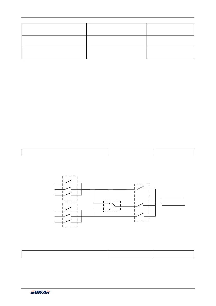
7.2 RUNNING COMMAND SELECTION (GROUP F0.1)
F0.1.15 Control place selection Setting range: 0, 1, 2 Factory default: 0
This function defines three kinds of modes for selecting the control command source, as shown in Figure 7-7:
Operating panel
MODBUS fieldbus
F0.3.33
Control command 1
F0.3.34
Control command 2
F0.1.15
Selection of control
command source
External control
terminal
Control command 1
effective
Selection of multifunctional input
terminal (ON/OFF) (function no.
11, set by the F3.0 group
parameters)
Control command
Operating panel
MODBUS fieldbus
External control
terminal
Control command 2
effective
F0.1.16 Selection of frequency set value Setting range: 0~14 Factory default: 0
The V560 series inverter has two frequency setting sources (corresponding parameters F0.2.25, F0.2.26).
This parameter determines 14 kinds of combined calculation methods for the two frequency setting sources.
Figure 7-8 shows the structure sketch of the frequency setting channel.
The actual running direction of the inverter is the result of “XOR” between the set value direction (always
being FWD direction for single polarity setting) and the running command direction.
Figure 7-7 Sketch of selecting the control command sources