Description Of Specific Functions 189
V560 Series High Performance Closed-Loop Vector Inverter User Manual
Fb.2.46 Spindle transmission ratio
Setting range:
0.010~50.000
Factory default: 1.000
When the encoder is not directly installed on the spindle, this parameter needs need to be set to achieve
correct spindle orientation. This parameter only functions for the spindle orientation function.
Spindle transmission ratio = revolution of the speed shaft: spindle revolution.
7.43 VIRTUAL INPUT AND OUTPUT (GROUP FF.0)
FF.0.00 FF configuration parameter
locking function (H)
Setting range: 0000~1001 Factory default: 0000
FF group parameters include special and internal function parameters, and their setting and initialization are
confined. This group of parameters is used to set the user’s
authority for operating FF parameters.
FF.0.01~FF.0.08 Definition of
virtual output node (SDO1~SDO8)
Setting range: 0~71 Factory default: 0
The virtual output nodes SDO1~SDO8 are functionally the same as the multifunctional output terminals
DO1~DO3, but do not output any signal. They are directly connected in the controller of the inverter to the
virtual input nodes SDI1~SDI8 one to one.
Using virtual nodes can not only help simplify wiring but can also avoid interference. The function of SDO1~
SDO8 can be defined by setting the value of FF.0.01~FF.0.08. Please refer to Table 2 (Comparison Table for
Variables of Multifunctional Output Terminals (DO/EDO/SDO) for the variables corresponding to the set
value.
FF.0.09~FF.0.16 Definition of virtual
input node (SDI1~ SDI8)
Setting range: 0~96 Factory default: 0
The virtual input nodes SDI1~SDI8 are functionally the same as the multifunctional input terminals DI1~DI9.
But there are no actual physical input nodes. They are connected to the virtual output SDO1~SDO8 one to
one, and are directly taken from the virtual output signal.
The virtual input nodes SDI1~SDI8 are functionally programmable, and their function can be defined by
setting the values of FF.0.09~FF.0.16. Please refer to Table 1 (Comparison Table for Functions of
Multifunctional Input Terminals (DI/EDI/SDI) for functions corresponding to the set value.
FF.0.17 Virtual output - input
connection polarity
Setting range: 0000~1111 Factory default: 0000
FF.0.18 Virtual output - input
connection polarity
Setting range: 0000~1111 Factory default: 0000
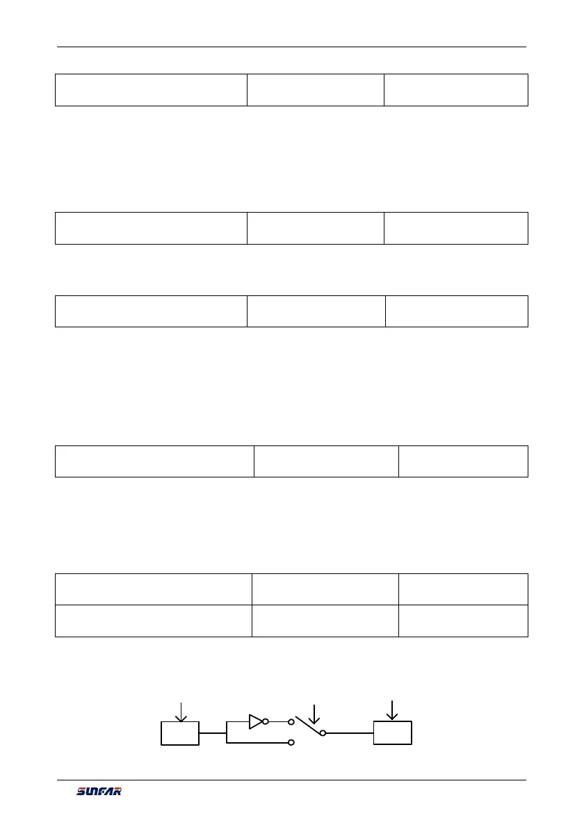
The parameters are used to set the connection logic status of the virtual output nodes SDO1~SDO8 and
virtual input nodes SDI1~SDI8. When it is set to be reverse polarity connection, the virtual output signal will
be negated before being inputted to the virtual input port, as shown in Figure 7-67.
FF0.17~FF0.18 FF0.09~FF0.16FF0.01~FF0.08
SDO
X
SDI
X
Figure 7-67 Block diagram of virtual output – input