Description Of Specific Functions 129
V560 Series High Performance Closed-Loop Vector Inverter User Manual
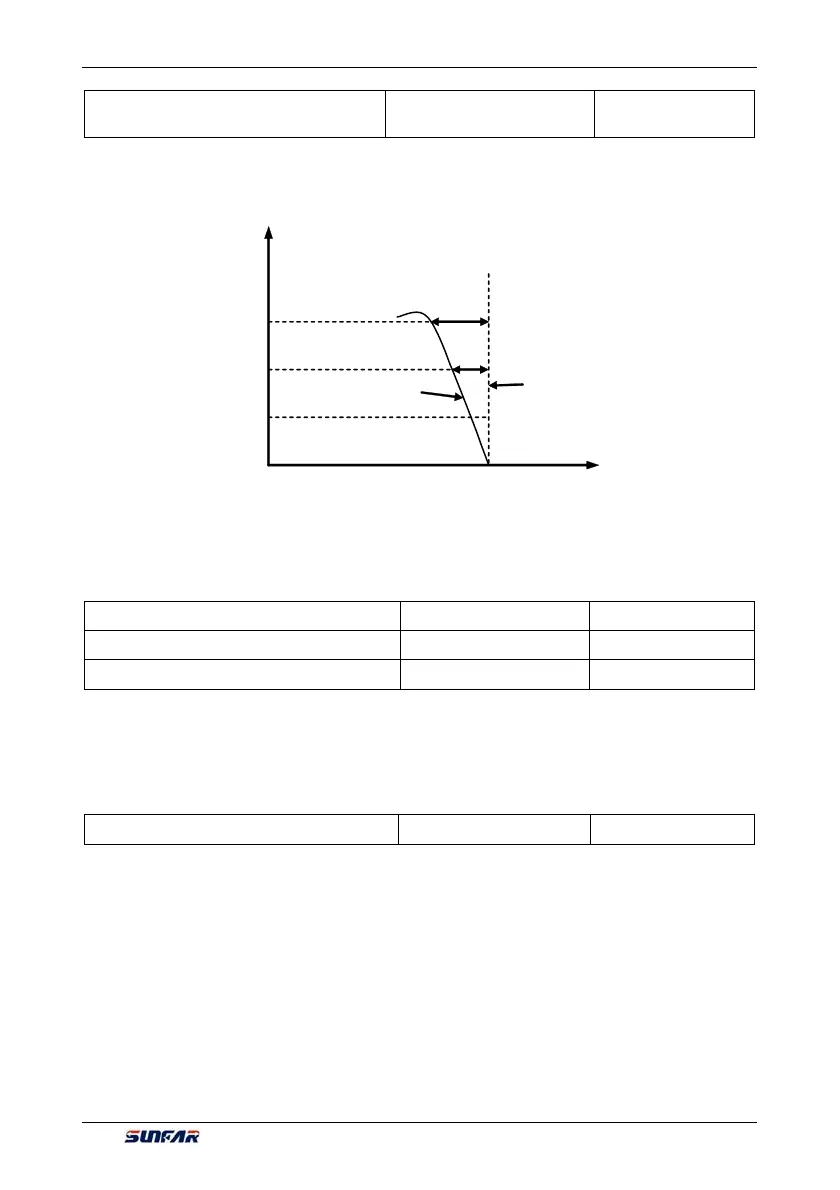
F1.2.25 Slip frequency compensation
for motor 1
Setting range: 0~150% Factory default: 0
The actual revolution difference of the motor may vary with the change of the load. Through setting of this
parameters, the inverter will automatically adjust the inverter's output frequency according to the load, so as
to offset the influence of the load to the motor revolution.
This parameter is only effective to V/F control mode.
7.9 V/F PARAMETERS AND OVERLOAD PROTECTION (MOTOR 2)
(GROUP F1.3)
F1.3.27 Reference frequency of motor 2 Setting range: 0~150% Factory default: 0
….
F1.3.37 Reference voltage of motor 2 Setting range: 0~150% Factory default: 0
The V/F control parameter when the motor 2 is selected is defined the same as parameters F1.2.15~
F1.2.25
.
7.10 STEADY RUNNING (GROUP F1.4)
F1.4.39 Accel/decel current limit level Setting range:120~180% Factory default: 160
When the frequency inverter is in acceleration and deceleration running, for the acceleration and
deceleration time does not match to the motor inertia or load breaks, there can be phenomenon of steep
current rise. This parameter is used for setting the allowed output level when frequency inverter is in state of
acceleration. Setting value is the relevant percentage of rated output current of frequency inverter.
When the output current of frequency inverter exceeds the specified level of this parameter, acceleration and
deceleration time will be automatically delayed, to ensure the output current limited within the range of this
level, refer to the figure below. Thus, for occasions requiring shorter acceleration time, acceleration torque
level shall be properly improved.
Output current
Slip compensation is 100%
fter slip
compensation
Motor revolution
50%
100%
150%
Before slip compensation
Figure 7-29 Slip frequency compensation sketch