Description Of Specific Functions
V560 Series High Performance Closed-Loop Vector Inverter User Manual
190
7.44 PROTECTING FUNCTION CONFIGURATION PARAMETERS
(GROUP FF.1)
This group of parameters is used to define if the protecting function needs to be activated or not. Generally
no modification is required.
7.45 CORRECTION PARAMETERS (GROUP FF.2)
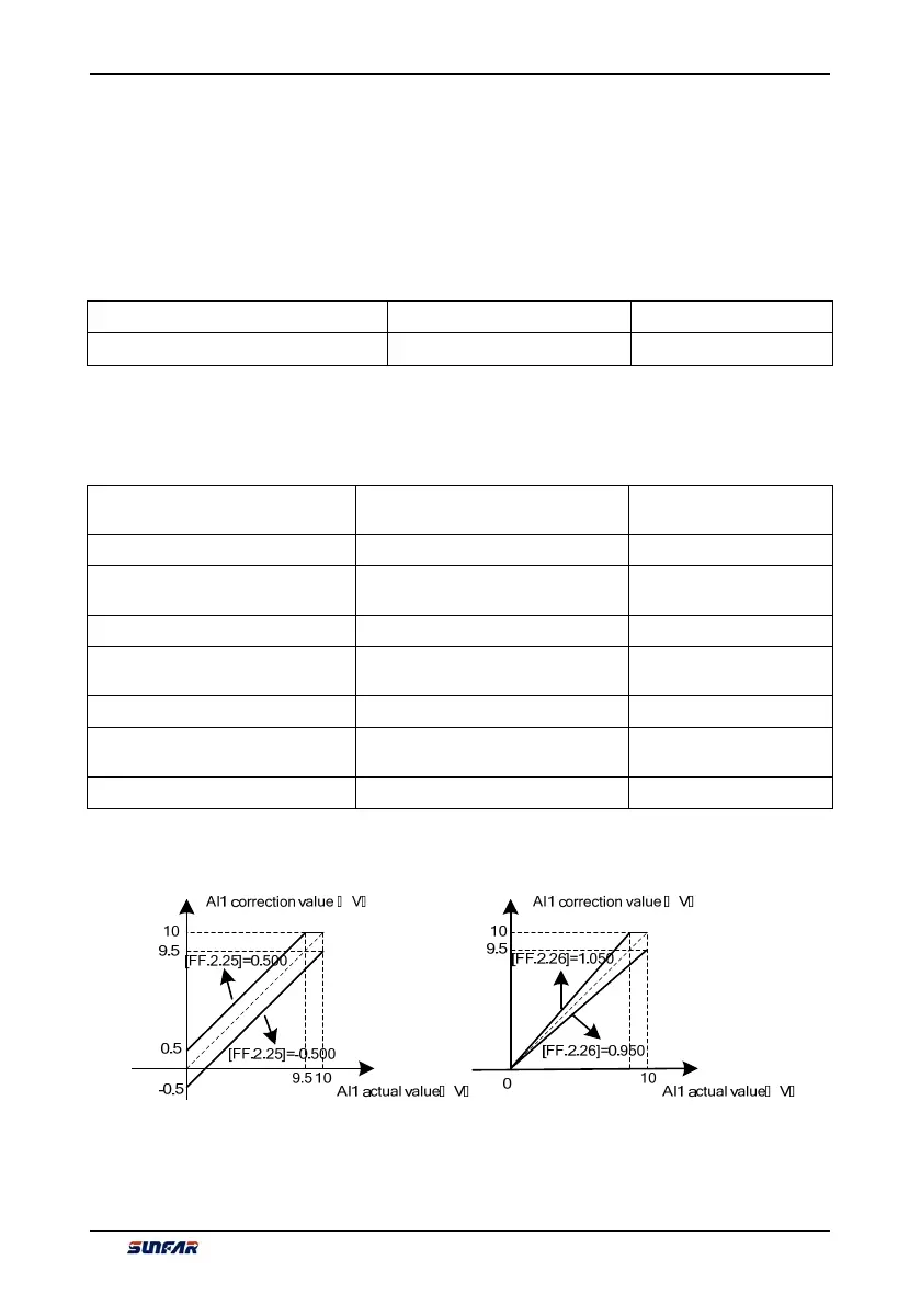
FF.2.25 AI1 Zero offset adjustment Setting range: -0.500~0.500V Factory default: 0.0
FF.2.26 Al1 gain correction Setting range: 0.950~1.050 Factory default: 1.000
This group of parameters is sued to make fine adjustment to AI1 zero point and AI1. The relationship before
and after adjustment:
AI1 input value= AI1 gain correction* AI1 value before adjustment +AI1 zero offset
FF.2.27 4mA deviation
adjustment for AI2
Setting range: -0.500~0.500mA Factory default: 0.0
FF.2.28 Al2 gain correction Setting range: 0.950~1.050 Factory default: 1.000
FF.2.29 AI3 Zero offset
adjustment
Setting range: -0.500~0.500V Factory default: 0.0
FF.2.30 Al3 gain correction Setting range: 0.950~1.050 Factory default: 1.000
FF.2.31 AO1 zero offset
correction
Setting range: -0.500~0.500V Factory default: 0.0
FF.2.32 AO1 gain correction Setting range: 0.950~1.050 Factory default: 1.000
FF.2.33 AO2zero offset
correction
Setting range: -0.500~0.500V Factory default: 0.0
FF.2.34 AO2 gain correction Setting range: 0.950~1.050 Factory default: 1.000
The correction principle for each analog input/output port is the same as AI1. The relationship curves with
zero offset adjustment and gain correction are respectively as below. Generally, users do not need to set
these parameters.
Figure 7-68-A AI1 zero offset
correction curve
Figure 7-68-B AI1 gain
correction curve