Functional Parameter Table
V560 Series High Performance Closed-Loop Vector Inverter User Manual
93
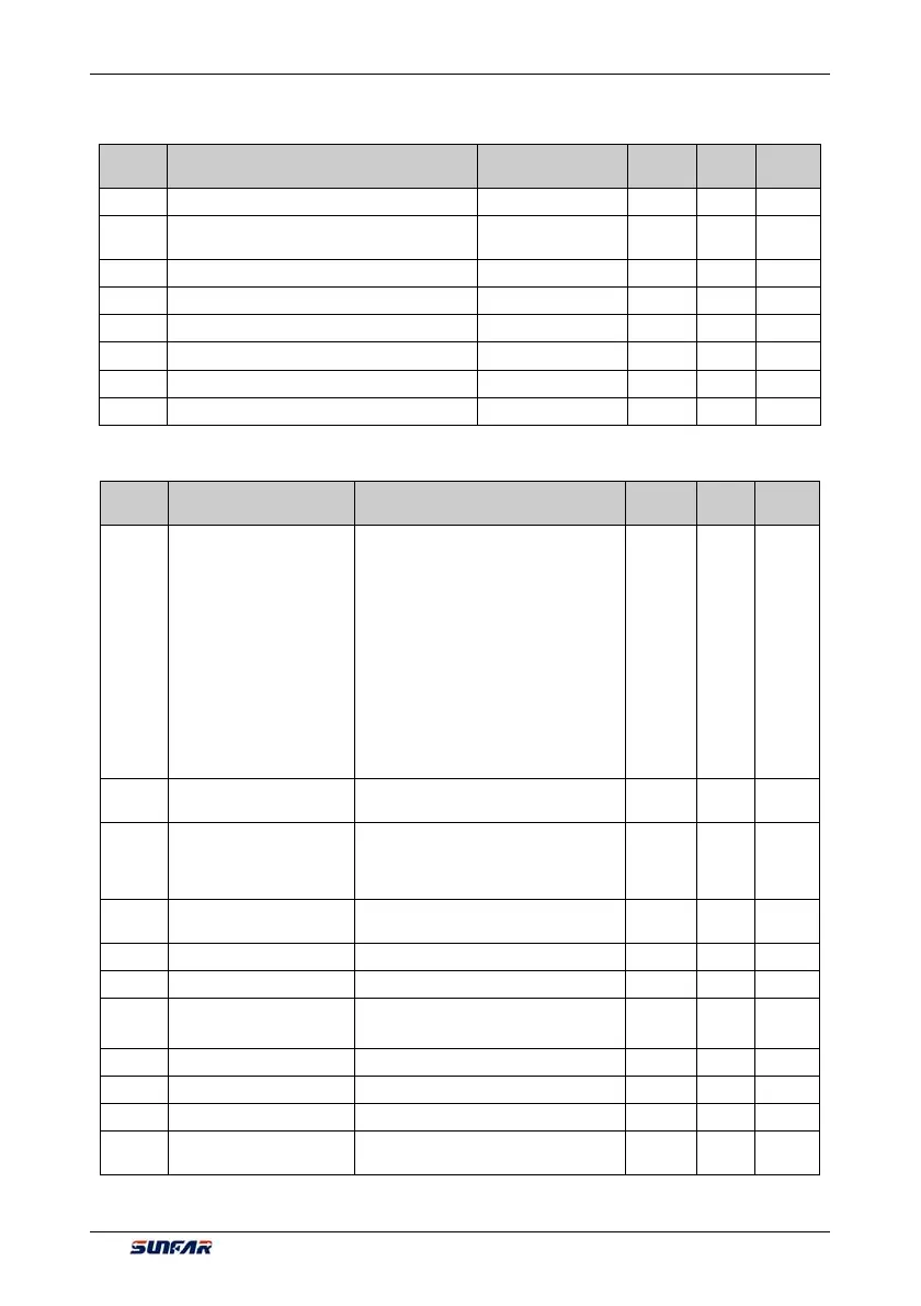
6.2.58 SPINDLE CONTROL AND SCALE POSITIONING STATUS PARAMETER
Function
Code
Name
Setting Range and
Description
Minimum
Unit
Factory
Default
Change
Limit
d1.2.16 Spindle (PG installation shaft) position angle 0~359.9 R
d1.2.17
Spindle (PG installation shaft ) traveling circle
number
0~65535 R
d1.2.18 Accumulative number of position pulse (low) 0~65535 R
d1.2.19 Accumulative number of position pulse (middle) 0~65535 R
d1.2.20 Progressive distance 0.0~5000.0mm R
d1.2.21 Set position pulse( low) 0~65535
R
d1.2.22 Set position pulse(middle) 0~65535
R
d1.2.23 Set position pulse(high) 0~65535
R
6.2.59 EQUIPMENT INFORMATION
Function
Code
Name Setting Range and Description
Minimum
Unit
Factory
Default
Change
Limit
d1.4.40
Expansion module
connection information
_ _ _ X: Reserved
_ _ X _: Standard expansion board
0: Not connected
1: Connected
_ X _ _: Functional expansion board 1
0: Not connected
1~F: Connected (the value stands for the
type of expansion board)
X _ _ _: Functional expansion board 2
0: Not connected
1~F: Connected (the value stands for the
type of expansion board)
1 — R
d1.4.41
Total quantity of panel
communication information
0~65535 1 — R
d1.4.42
Number of panel
communication CRC check
errors + number of errors
accepted
0~65535 1 — R
d1.4.43
Number of effective data of
panel communication
0~65535 1 — R
d1.4.44 Equipment model Reserved 1 — R
d1.4.45 Equipment capacity 0.1~1000.0KW 0.1KW — R
d1.4.46
Motherboard program
version (H)
6000~6999 1 — R
d1.4.47 Reserved 1 — R
d1.4.48 Motherboard check date(H) 2009~2100 1 — R
d1.4.49 Motherboard check date(H) 0101~1231 1 — R
d1.4.50
Motherboard check serial
number
0 ~ 50000 1 — R