14 Installation Of Frequency Inverter
V560 Series High Performance Closed-Loop Vector Inverter User Manual
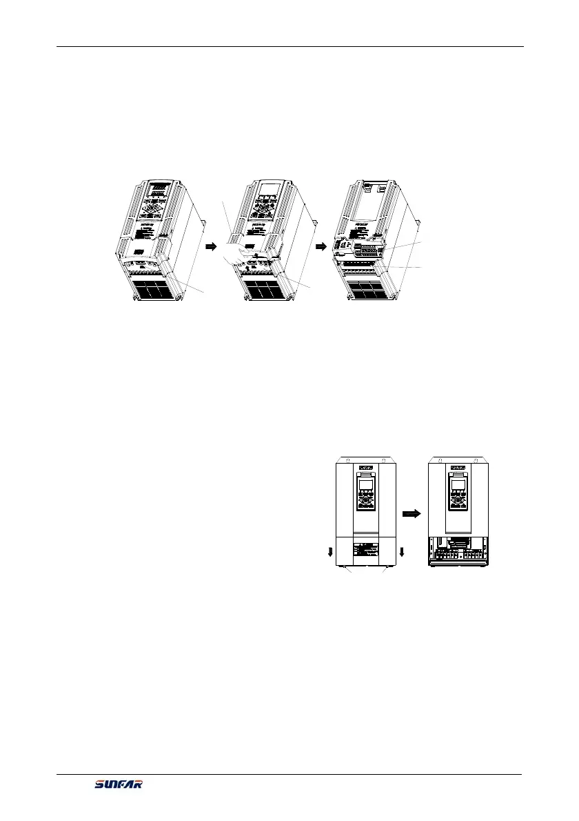
3.3 DISASSEMBLY AND INSTALLATION OF TERMINAL COVER
3.3.1 DISASSEMBLY AND INSTALLATION OF PLASTIC COVER PLATE
y Disassembly:
Put finger on the handle slot at the bottom of cover plate (the position of clasp as Figure 3-4), and forcibly lift
it upward until the card clasps between cover plate and shell break away, then pull the cover plate down can
disassemble the shell. Shown as Figure 3-4.
y Installation:
Slant cover plate into about 15°, then insert the fixed stator at the top of cover plate into fixed slot on shell.
Forcibly press the cover plate down until heard a click, which means the cover plate has been in place.
3.3.2 DISASSEMBLY AND INSTALLATION OF SHEET-METAL COVER PLATE
Disassembly and installation of sheet-metal cover plate are as shown in Figure 3-5.
y Disassembly:
1. Undo the two thumb screws at the bottom of cover
plate;
2. Translate the cover plate outward along direction of
icon then can dismantle it.
y Installation:
1. Place the cover plate down parallel to the chassis, to
make cover plate just seize up the both sides of
chassis;
2. Push cover plate forward along direction of icon, to
make the stator at the top of cover plate insert into
the fixed slot on shell;
3. Tighten up the two thumb screws at the bottom of cover plate.
Lower cover plate
Front plugboard
Major loop
terminal
Control loop
terminal
Position of
handle clasp
captive screw
Figure 3-5 Schematic diagram of disassembly
and installation of sheet-metal cover plate
Figure 3-4 Disassembly and installation schematic diagram of plastic terminal cover