16 Installation Of Frequency Inverter
V560 Series High Performance Closed-Loop Vector Inverter User Manual
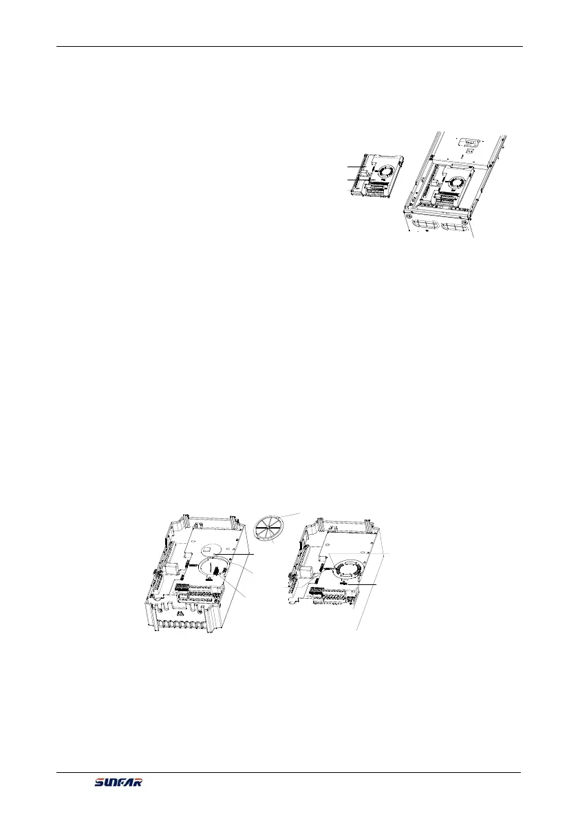
3.5 DISASSEMBLY AND INSTALLATION OF EXPANSION BOARD
Please refer to Figure 3-6 for disassembly and installation of expansion board.
y Installation:
1. Place expansion board in direction as shown in
figure, press down until good connection between
expansion board and socket of control panel;
2. Tighten the fastening screw M3 at the left upper
corner of the expansion card
y Disassembly:
1. Loosen the fastening screw M3 at the left upper
corner of the expansion card;
2. Pull expansion board up (as shown in Figure 3-16)
out from the socket of control panel.
3.6 INSTALLATION AND DISASSEMBLY OF FUNCTION BOARD
3.6.1 The installation of type I function card
Function board is installed on control panel with utilization of extension cord. As shown in Figure 3-7-A.
Apply to the inverter model above V560-4T0030G/4T0040P.
y Installation:
1. After making the triangle mark on cylindrical cover plate direct to “open”, put index finger or middle finger
into the hole to push upward, then can take the circular cover plate out;
2. Make the socket of function board direct to the pin of control board, and then slightly press it down until
good contact;
3. Get cylinder cover plate on and rotate clockwise to make the triangle on it direct to “lock”.
Functional expansion
board
Socket
Contact pin
Cover plate
Cylinder
Triangular
indication
Opened position
of cover plate
Closed position
of cover plate
y Disassembly:
1. Clockwise rotate cylinder to make the triangle on it direct to “open”, put index finger or middle finger into
the hole, push up then can take the cylindrical cover plate out
2. Slightly pull the pin of control board up out from function board then can take it out.
PG expansion
board
Control box
I/O expansion
board
Figure 3-7-A Schematic diagram of installation and disassembly of type I function board
Figure 3-6 Schematic diagram of installation
and disassembly of expansion board