214 Example of Usage
V560 Series High Performance Closed-Loop Vector Inverter User manual
second part)
16. F9.0.05= 0.2
Differential coefficient of PID in first part
17. F9.0.06= 5
Differential inertia filtering time PID in first part
18. F9.0.07= 1 Offset PID output of Inertia filtering time
19. F9.0.08= 0 Offset PID internal figure setup
20. F9.0.11= 62.5
Offset PID internal figure given= (R+r)*F/2T*100%
21. F9.0.12= 0 Offset PID feedback selects analog quantity Al1
22. F9.0.13= 0
Feedback input being 0V contrary to 0% feedback
23. F9.0.14= 8.3
Feedback input contrary to 100% feedback= Fm*(R+r)/ 2T*10, (Fm: full-scale
tension value of tension sensor; tension sensor output signal: 0-10V.
24. F9.0.15= (R + r)/2
Feedback multiplication factor transform feedback tension signal into torque
signal depending on feedback factor
25. F9.1.21= 0011
Offset PID selects double-PID parameter switch PID parameter according to
feedback value
26. F9.1.23= 0060
Feedback value of lower-limited switching value 60%
27. F9.1.24= 0080
Feedback value of top-limited switching value 80%
28. F9.1.29= 2
Proportional gain of PID in second part
29. F9.1.30= 18
Integral time of PID in second part
30. F9.1.31= 0.5
Differential coefficient of PID in second part
31. F9.1.33= 5 Regulator output of filtering time constant
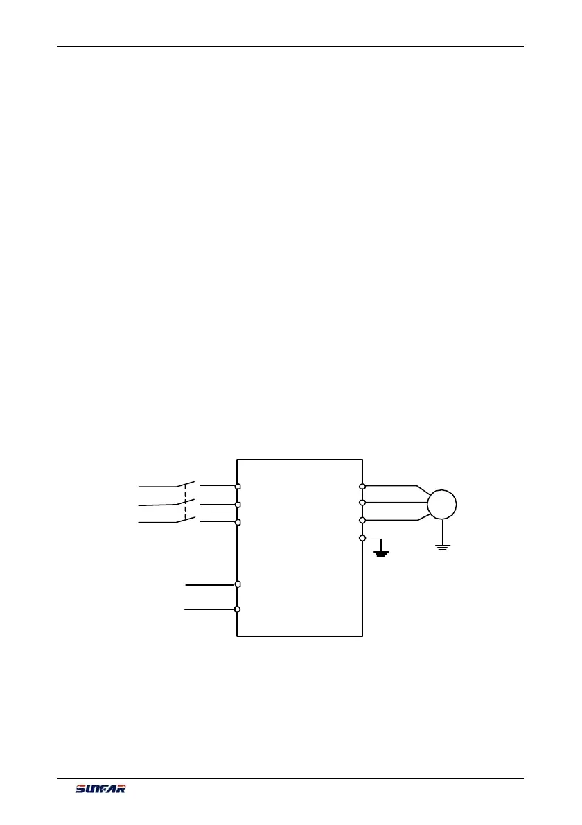
10.2.4 WIRING DIAGRAM
M
motor
U
W
V
R
S
T
E
Tensiondetecting
sensor
AI1
GND
×
×
×
Three-phase
circuit breaker
Three-phase
power supply