124 Description Of Specific Functions
V560 Series High Performance Closed-Loop Vector Inverter User Manual
7.6 ACCEL AND DECEL CHARACTERISTICS (GROUP F1.0)
F1.0.00 Acceleration and
deceleration modes
Setting range: 0000~0011 Factory default: 0000
_ _ _ X : Accel and decel mode
0: Liner acceleration and deceleration
The output frequency of the inverter increases or decreases according to fixed speed. The output frequency
has liner relationship with the acceleration and deceleration time, and steadily increases or decreases
according to constant gradient.
1: S curve acceleration and deceleration
The output frequency of the inverter increases or decreases according to grading speed, and the
characteristics of S curve is determined by the parameter [F1.0.01] and [F1.0.02]. This function is mainly to
reduce noise and ventilation during acceleration and deceleration, and decrease impact of the starting and
stop load. When the load inertia is excessive, leading to overload fault during deceleration, it can be
improved by adjusting the parameter setting ([F1.0.01] and [F1.0.02]) of S deceleration curve, so as to
reasonably adjust the deceleration rate at different frequency.
_ _ X _: Accel and decel unit
0: Sec. (Second)
The acceleration and deceleration time is in the unit of second, and is at factory default value.
1: Min. (Minute)
The acceleration and deceleration time is in the unit of minute.
F1.0.01 % of S curve at the
bottom
Setting range: 5.0~100.0-[F1.0.02] Factory default: 15.0
F1.0.02 % of S curve at mid
secion
Setting range:
20.0~100.0-[F1.0.01]
Factory default: 70.0
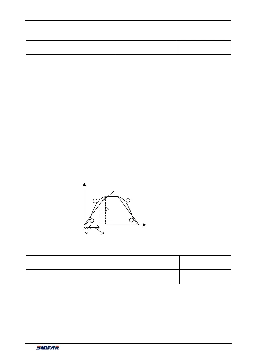
Define the curve parameters of acceleration and deceleration of S curve.
As shown in item in Figure 7① -24, the acceleration starting/deceleration ending period of S curve is
indicated by the percentage of the total acceleration and decoration time.
As shown in item in Figure 7② -24, the acceleration rising/deceleration decreasing period of S curve is
indicated by the percentage of the total acceleration and decoration time.
2
S Curve
Time
(Sec./min.)
Output frequency(Hz)
[F0.0.01] [F0.0.02]
Straight line
2
1
1
Figure 7-24 Acceleration and deceleration curve
 Loading...
